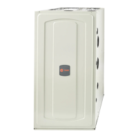
Do you have a question about the American Standard L8V1A040U3VSAA and is the answer not in the manual?
Warnings about fire or explosion risks due to improper handling of fuel or appliances.
Warnings about explosion risks from gas leaks and the need for detection devices.
Warning about hazards from improper electrical servicing and safety precautions.
Warnings about CO poisoning from improper venting and new furnace installations.
Warning against installing the furnace directly on carpeting, tile, or other combustible material.
Warning about chemical exposure from the product, including lead.
Warning against attempting to manually light the furnace.
Hazards related to electrical shock, installation approvals, and gas connectors.
Hazards concerning failure response procedures and flammable material storage.
Hazards related to improper door closure or maintenance for CO poisoning.
Warnings about high voltage, moving parts, and disconnect switch procedures during installation.
Safety regarding filter placement, servicing, and overheating/explosion events.
Warnings about carbon monoxide hazards related to chimney venting and liner integrity.
Cautions on voltage connection, corrosion, sharp edges, and tool usage.
Cautions regarding preventing freeze-up of water pipes during furnace shutdown in cold weather.
Cautions on ignition function, water damage prevention, and hot surfaces.
Cautions for furnace service, use as construction heater, and equipment damage from UV light.
Details of items included in the document pack for the furnace.
Essential safety practices and precautions to be followed during furnace installation and servicing.
Manufacturer's disclaimer and general recommendations for furnace installation and compliance.
Instructions on how to remove the front panel of the L8V1 furnace.
Guidelines for installing the furnace in a horizontal position in attics or crawlspaces.
Classification of furnaces and requirements for venting systems.
Guidelines for venting into masonry chimneys, including liner requirements.
Conditions for venting into lined, internal masonry chimneys.
Recommended practices to minimize corrosion in external masonry chimneys.
Requirements for gas vent termination height based on roof pitch or vertical wall distance.
Instructions for connecting supply ducts to an upflow furnace with a coil.
Instructions for connecting supply ducts to a horizontal left furnace with a coil.
Instructions for connecting supply ducts to a horizontal right furnace with a coil.
General guidelines for return duct connections, including restrictions and requirements.
Installation for upflow furnace with bottom return and remote filter in a closet.
Installation for upflow furnace with bottom return and filter box in a closet.
Installation for upflow furnace with bottom return on a ducted pedestal.
Installation for upflow furnace with bottom return on a ducted pedestal with filter box.
Installation for upflow furnace with pedestal, side return, and filter box.
Installation for upflow furnace with a single side return.
Installation for upflow furnace with two side returns.
Information on filter types, sizes, and external installation requirements.
Steps for preparing upflow furnaces for bottom and side return air filter installations.
Diagram and notes for field wiring a single-stage thermostat to the IFC and outdoor unit.
Includes preliminary inspections and lighting instructions for unit startup.
Procedure for completely shutting off the furnace and its electrical supply.
Guidance on adjusting and checking control and safety switches, including limit switches.
Approved venting options for upflow furnace installations.
Approved venting options for horizontal left furnace installations.
Approved venting options for horizontal right furnace installations.
Instructions for converting inducer venting for upflow orientation with top venting.
Instructions for converting inducer venting for upflow with left side exhaust.
Instructions for converting inducer venting for upflow with right side exhaust.
Instructions for horizontal left orientation with left side venting.
Instructions for converting inducer venting for horizontal left with top exhaust.
Instructions for converting inducer venting for horizontal right with right side exhaust.
Instructions for converting inducer venting for horizontal right with top exhaust.
Overview of the IFC control system menu, including settings and options.
Settings for outdoor unit tonnage and type compatibility with furnace models.
Gas heating CFM settings adjusted by model for optimal heat rise.
Display codes for inducer status, system modes, and calculated airflow.
Codes for menu options including alarms, delays, and system settings.
Procedure for viewing, clearing, and resetting fault codes and factory defaults.
Timing sequences for EAC relay and HUM relay operations during blower and heating cycles.
Step-by-step operation sequence for gas heating, including safety checks and burner ignition.
Step-by-step operation sequence for single stage cooling, including thermostat calls and blower operation.
Operation sequence for two-stage cooling, including thermostat and airflow stages.
Operation sequence for single-stage heat pump heating, including thermostat and airflow stages.
Operation sequence for two-stage heat pump heating, including thermostat and airflow stages.
| Brand | American Standard |
|---|---|
| Model Number | L8V1A040U3VSAA |
| Category | Furnace |
| Type | Gas |
| Heating Capacity | 40, 000 BTU |
| Input BTU | 40, 000 BTU |
| Output BTU | 32, 000 BTU |
| Stages | Single Stage |
| Blower Motor Type | Multi-Speed |
| Fuel Type | Natural Gas |
| Installation Type | Upflow/Horizontal |
| Warranty | 10 Years |
| Efficiency Rating | 80% AFUE |


 Loading...