EasyManua.ls Logo

American Standard BAYLIFT002A User Manual

American Standard BAYLIFT002A
24 pages
To Next Page IconTo Next Page
Page #1 background imageLoading...
Page #1 background image
All phases of this installation must comply with the NATIONAL, STATE & LOCAL CODES. In the absence of local codes, the
installation must conform with National Electric Code -- ANSI/NFPA 70 or "LATEST REVISION."
Since the manufacturer has a policy of continuous
product improvement, it reserves the right to change
specifications and design without notice.
© American Standard Inc. 1999
HAZARDOUS VOLTAGE - DISCONNECT POWER BEFORE SERVICING
WARNING:
INSTALLATION
OPERATION
MAINTENANCE
ALL phases of this installation must comply with
NATIONAL, STATE AND LOCAL CODES
IMPORTANT — This Document is customer property and is to remain with this unit. Please return to service information pack upon completion of work.
Single Package Two Stage
Gas/Electric 16 SEER
Convertible 3 & 5 Ton
Model:
YCZ036F1/3M0B
YCZ060F1/3M0B
BAYLIFT002A
LIFTING LUG KIT
18-EB21D4-2
Library
Product Section
Product
Model
Literature Type
Sequence
Date
File No.
Supercedes
Service Literature
Unitary
Packaged Gas/Electric
YCZ
Installation, Operation, Maintenance
1A
July 1999
SV-UN-RT-YCZ-IOM-1A 7/99
YCZ-IOM-1
YCZ-IOM-1A
Question and Answer IconNeed help?

Do you have a question about the American Standard BAYLIFT002A and is the answer not in the manual?

American Standard BAYLIFT002A Specifications

General IconGeneral
Model NumberBAYLIFT002A
CategoryFurnace
BrandAmerican Standard
TypeGas Furnace
Fuel TypeNatural Gas
Product TypeFurnace

Summary

GENERAL INFORMATION

INSPECTION

Check unit condition upon arrival and verify specifications.

PRECAUTIONARY MEASURES

Safety guidelines for handling hazardous materials and avoiding exposure.

FIRST AID MEASURES

Procedures for immediate response to eye or skin contact with materials.

DIMENSIONAL DATA

YCZ036,060F OUTLINE – BACK

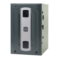
Diagram showing external dimensions and key features from the rear.

YCZ036,060F OUTLINE – FRONT

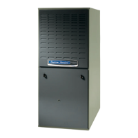
Diagram showing external dimensions and key features from the front.

LOCATIONS AND RECOMMENDATIONS

HORIZONTAL AIRFLOW APPLICATION

Guidelines for unit placement and airflow for horizontal installations.

CLEARANCES

Recommended spacing for proper operation, service, and efficiency.

DOWNFLOW APPLICATION -- CURB MOUNTING

Instructions for installing the unit on a roof curb.

INSTALLATION

LOCATION AND CLEARANCES

Selecting an appropriate site and ensuring necessary clearances.

PLACING AND RIGGING

Safe methods for lifting, moving, and positioning the unit.

PLACING THE UNIT ON A MOUNTING CURB

Specific steps for setting the unit onto a roof mounting curb.

ROOFTOP -- UNITS

Procedures for rooftop installation using a frame or curb.

GROUND LEVEL -- HORIZONTAL UNITS

Procedures for ground-level installation.

CONDENSATE DRAIN PIPING

Requirements and methods for installing the condensate drain line.

DUCTWORK

ATTACHING DOWNFLOW DUCTWORK TO ROOF CURB

Connecting ductwork for downflow rooftop installations.

ATTACHING HORIZONTAL DUCTWORK TO UNIT

Connecting ductwork for horizontal installations.

GAS PIPING INSTALLATION

PIPE DELIVERY SCHEDULE

Procedure for determining gas pipe size based on input and length.

GAS PRESSURE SET-UP PRECAUTIONS

Safety warnings and precautions for gas pressure testing.

GAS SUPPLY LINE PRESSURE

Guidelines for setting and maintaining correct gas supply pressure.

MANIFOLD PRESSURE

How to check and adjust the gas manifold pressure.

INPUT CHECK AND ADJUSTMENT

HIGH ALTITUDE INSTALLATION

Adjustments required for units installed at higher elevations.

FILTER INSTALLATION

AIR FILTERS

Information on installing and using air filters with the unit.

ELECTRICAL WIRING

POWER SUPPLY AND WIRING

Requirements for proper electrical power supply and connections.

GROUNDING AND CONTROL WIRING

Essential procedures for grounding and low-voltage control connections.

THERMOSTAT HEAT ANTICIPATOR

Setting the heat anticipator for thermostat operation.

YCZ-F FIELD WIRING DIAGRAM

Schematic illustrating electrical connections for the unit.

START - UP

PRE-START QUICK CHECKLIST

Comprehensive checklist before initiating unit operation.

STARTING THE UNIT IN THE COOLING MODE

Step-by-step procedure for starting the unit in cooling.

HEATING CYCLE

Procedure for starting and operating the unit in heating mode.

SEQUENCE OF OPERATION

HEATING CYCLE

Detailed operational logic for the heating cycle stages.

COOLING CYCLE

Detailed operational logic for the cooling cycle stages.

ICM FAN MOTOR ADJUSTMENTS

How to adjust fan motor speed settings.

TROUBLESHOOTING

IGN LED DIAGNOSTIC INDICATOR

Interpreting LED flash codes for system diagnostics.

TROUBLESHOOTING CHART

Guide to identifying and resolving common system faults.

MAINTENANCE

ROUTINE MAINTENANCE BY OWNER

Periodic maintenance tasks that owners can perform.

CONDENSER COIL

Instructions for cleaning the condenser coil.

SERVICEMAN MAINTENANCE CHECKS

Professional service checks for cooling and heating seasons.

FLUE CLEANING

Procedure for inspecting and cleaning the flue system.

LIMITED WARRANTY

Related product manuals