EasyManua.ls Logo

American Standard YCD121 - User Manual

American Standard YCD121
20 pages
Print Icon
To Next Page IconTo Next Page
Loading...
1
YC-IOM-4G
18-EB60D11-7
Library Service Literature
Product Section Unitary
Product Rooftop Lt. Comm.
Model YC
Literature Type Installation/ Oper/ Maint
Sequence 4G
Date August 1998
File No. SV-UN-RT-YC-IOM-4G 8/98
Supersedes YC-IOM-4F
Since the manufacturer has a policy of continuous product improvement, it reserves the right to
change specifications and design without notice. The installation and servicing of the
equipment referred to in this booklet should be done by qualified, experienced technicians.
© American Standard Inc. 1998
Packaged Gas/Electric
8-1/2 thru 25 Ton
INSTALLATION
OPERATION
MAINTENANCE
Customer Property — Contains wiring, service,
and operation information. Please retain.
Models: (60 Hz) (50 Hz)
YC*102-301 YC*085-250
IMPORTANT NOTE: All phases of this installation must comply with the NATIONAL, STATE & LOCAL CODES. In
addition to local codes, the installation must conform with National Electric Code -ANSI/NFPA NO. 70 LATEST REVISION.
These units are equipped with an electronic unit control processor, (UCP) that provides service functions which are
significantly different from conventional units. Refer to the TEST MODES and START-UP PROCEDURES before
attempting to operate or perform maintenance on this unit.
Question and Answer IconNeed help?

Do you have a question about the American Standard YCD121 and is the answer not in the manual?

Summary

Inspection

Unit Features

Self-test;Auto-configuration

System performs automatic tests to verify correct operation and configure itself upon power-up.

Cooling Minimum ON;OFF times

Enforces a minimum 3-minute ON/OFF time for compressor reliability to prevent short cycling.

Test Mode Procedures

Step Test Mode

Initiated by shorting test terminals, cycles through unit operational steps for diagnostics.

Auto Test Mode

Unit cycles through test steps automatically once upon jumper installation, each step lasting 30 seconds.

Resistance Test Mode

Initiated by applying resistance across test terminals, allowing selection of specific test steps for diagnostics.

Dimensional Data

Unit Dimensions

Provides detailed measurements of unit dimensions and critical points for installation planning.

Location and Recommendations

Location and Clearances

Specifies requirements for unit placement, airflow, and service access to ensure optimal performance.

Placing and Rigging

Instructions for safely lifting and positioning the unit using appropriate rigging techniques.

Attaching Downflow Ductwork to Roof Curb

Gas Piping Installation

Evaporator Fan Adjustment

Power Wiring

Start-Up

Pre-Start Quick Check List

A comprehensive checklist to verify all installation and safety requirements are met before initial operation.

Power-up Initialization

Starting the Unit in the Heating Mode

Starting The Unit In The Cooling Mode

Compressor Overload Protection

Final Installation Checklist

Overview

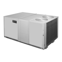
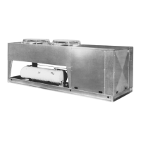
This document is an installation, operation, and maintenance manual for the YC-IOM-4G 18-EB60D11-7 Packaged Gas/Electric Unit, designed for rooftop light commercial applications. It covers models YC*102-301 (60 Hz) and YC*085-250 (50 Hz), with capacities ranging from 8-1/2 to 25 tons.

Function Description:

The YC-IOM-4G unit is a self-contained packaged gas/electric heating and cooling system designed for outdoor mounting, typically on a roof or at ground level. It provides both heating and cooling functions for a commercial space. The system is managed by a Unitary Control Processor (UCP), which is the "heart of the system," containing the computer program and performing self-diagnostics, component identification, and system configuration at power-up. The UCP interacts with various modules and sensors to control the unit's operation, including a Zone Sensor Module (ZSM) for temperature sensing and operator controls, a Unitary Economizer Module (UEM) for economizer accessory connection, and a Communication Interface (TCI) for integration with building management systems. The unit features a vertical condenser discharge and is designed for outdoor operation, eliminating the need for additional flue venting systems.

Important Technical Specifications:

  • Models Covered: YC*102-301 (60 Hz) and YC*085-250 (50 Hz).
  • Capacity: 8-1/2 to 25 tons.
  • Refrigerant: Contains an HCFC (R-22) refrigerant.
  • Gas Type: Shipped from the factory designed for natural gas only.
  • Gas Supply Pressure: Minimum permissible gas supply pressure for input adjustment is 3.5 inches water column (W.C.) for natural gas and 8 inches W.C. for LP gas. The unit should not be exposed to gas line pressures exceeding 14 inches W.C. (1/2 PSIG).
  • Manifold Pressure: Factory set at (negative) -0.2 inches W.C. for natural and LP gas.
  • Electrical Power: Designed for 230 VAC applications (208-230 volt units). Voltage variation should remain within nameplate limits.
  • Low Voltage Transformers: Units have integral circuit breakers. Replacement fuses for older models are 3.5 amps.
  • Compressors: Scroll compressors (103, 151, 181, 200, 211, 240, 241, 300, 301 units only) require proper electrical phasing for correct rotation.
  • Return Air Smoke Detector Airflow: For proper sensing, air velocity must be between 500 and 4000 feet per minute. Minimum allowable airflow for specific models (e.g., YCD103: 3400 CFM, YCD121: 4100 CFM, YCD181: 5300 CFM).
  • Ductwork Connections: Supply and return openings have curb flanges for easy installation. Ductwork sleeves must be attached to curb flanges before unit placement.
  • Condensate Drain: 3/4 inch PVC connection for YC, TC*085 - 120C units; 1 inch NPT female connection for all other units.
  • Minimum ON/OFF Times: 3 minutes minimum ON/OFF time for compressor reliability, enforced at power-up or re-application.
  • UCP Indicator Light: Red light in the lower left corner indicates correct UCP function (solid glow) or test mode operation (flashing).
  • Ignition Control Module: Two LEDs monitor heater operating status and set diagnostics.
  • Lead-Lag Function: Selectable configuration within the UCP to alternate compressor starting between refrigeration circuits.

Usage Features:

  • Self-test/Auto-configuration: At power-up, the unit performs tests to verify correct operation and automatically configures itself based on the wiring harness.
  • ZSM Modes: HEAT (heating only), AUTO (auto-changeover), OFF (no functions), COOL (cooling and economizer).
  • FAN Settings: AUTO (fan enabled only during heating/cooling) and ON (fan enabled at all times for minimum ventilation).
  • Test Modes:
    • Step Test Mode: Initiated by momentarily shorting "TEST" terminals (TEST 1 and TEST 2) on the low voltage terminal strip (LTB). Allows stepping through various test steps (e.g., Fan On, Economizer, Cool 1, Cool 2, Heat 1, Heat 2, Heat 3, Defrost, Em Heat). Each step can run for up to one hour.
    • Auto Test Mode: Initiated by installing a jumper across "TEST" terminals. Unit cycles through all test steps, changing every 30 seconds.
    • Resistance Test Mode: Initiated by applying specific resistance values across "TEST" terminals to select a desired test step.
  • Evaporator Fan Adjustment: Variable pitch pulley allows adjustment of fan RPM to achieve desired airflow rate based on external static pressure.
  • Compressor Overload Protection: External overload protection on specific circuits/units. Breakers trip and UCP locks out the compressor(s) upon overload detection.
  • Evaporator Defrost Control (EDC): Initiates a defrost cycle (approx. 3 minutes) when compressor run time reaches 10 minutes during low ambient operation (below 55°F for single fan, 40°F for dual fan units).

Maintenance Features:

  • Pre-Start Quick Check List: Comprehensive checklist for installers to ensure proper installation before start-up, covering location, ductwork, gas piping, condensate line, filters, wiring, grounding, and sensor placement.
  • Routine Maintenance by Owner: Includes replacing/cleaning air filters, cleaning the unit cabinet, clearing the condenser coil, and general unit inspection.
  • Season Maintenance (Cooling/Heating): Recommended annual check by a qualified serviceman, or more frequently if conditions warrant. Areas to examine include filters, motors, drive system components, economizer gaskets, condenser coils, safety controls, electrical components/wiring, condensate drain, and duct connections.
  • Smoke Detector Maintenance: Periodic checks and maintenance procedures are required to ensure proper function.
  • Troubleshooting: The manual provides warnings and notes for identifying and addressing issues such as improper electrical phasing, gas leaks, and fan motor adjustments.
  • Access Panels: Compressor compartment access panel and control box panel provide access for maintenance. Evaporator access panel must be closed during operation.

American Standard YCD121 Specifications

General IconGeneral
BrandAmerican Standard
ModelYCD121
CategoryHeat Pump
LanguageEnglish

Related product manuals