–5–
Remote Programming Information....................................................................................79
Remote Programming Advisory Notes ..............................................................................79
Section 23. SYSTEM COMMUNICATION .............................................................................................80
Report Code Formats..........................................................................................................80
Table of Contact ID Codes................................................................................................. .82
Section 24. SYSTEM OPERATION ........................................................................................................83
Security Codes................................................................................................................... .83
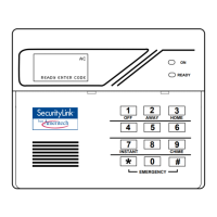
Keypad Functions.............................................................................................................. .84
Trouble Conditions .............................................................................................................86
Section 25. TESTING THE SYSTEM..................................................................................................... .87
Test Procedure................................................................................................................... .87
To the Installer...................................................................................................................88
Section 26. TROUBLESHOOTING GUIDE ............................................................................................89
Contacting Technical Support In The Event Of Problems...............................................91
REGULATORY AGENCY STATEMENTS ..........................................................................92
Section 27. SPECIFICATIONS & ACCESSORIES ................................................................................93
Specifications ......................................................................................................................93
Accessories (Compatible Devices)......................................................................................95
APPENDIX A. 5800 RF System Wireless Transmitters, Input Loop Identification Diagrams............ 96
Index.......................................................................................................................................................... .97
Limitations Of This Alarm System ...................................................................................................... . 102
Summary Of Connections.................................................................................................................... . 103
Limited Warranty .......................................................................................................................Back Cover
Programming Form ............................................................................................................................Insert
LIST OF FIGURES
Figure 1. Installing the Cabinet Lock ...............................................................10
Figure 2. Mounting The PC Board ....................................................................11
Figure 3. Mounting the PC Board & RF Receiver Together in the Cabinet ...11
Figure 4. Telephone Line Connections..............................................................12
Figure 5. Connection of 4300 Transformer to the Control Board....................13
Figure 6. Keypad Connections to the Control Board........................................15
Figure 7. Using a Supplementary Power Supply .............................................16
Figure 8. 2-Wire Smoke Detector Connected to Zone 1....................................18
Figure 9. 4-Wire Smoke Detector Connections (Zones 2–7).............................18
Figure 10. Glass Break Detector Connections to Zone 8 ....................................19
Figure 11. Wiring Connection, 4219 & 4229 (4229 shown) ................................21
Figure 12. 5881/5882 RF Receiver (cover removed) ...........................................24
Figure 13. 4229 Connections To Control.............................................................30
Figure 14. 4204 Connections To Control.............................................................30
Figure 15. 4300 Transformer Wiring Connections .............................................31
Figure 16. 4285/4286 Phone Module Wiring Connections ................................. 34
Figure 17. Typical Sounder Wiring .....................................................................37
Figure 18. Long Range Radio Connections ........................................................38
Figure 19A. Keyswitch Wiring (4300 Interface Transformer not used) ..............40
Figure 19B. Keyswitch Wiring (4300 Interface Transformer also used).............40
Figure 20. Connection of AAV Unit When Not Using a 4285 Phone Module .. 44
Figure 21. Connection of AAV Unit When Also Using a 4285 Phone Module .44
Figure 22. AM100 Summary of Connections ..................................................103