EasyManua.ls Logo

AMERITECH SecurityLink AM100 - User Manual

Default Icon
104 pages
Print Icon
To Next Page IconTo Next Page
Loading...
AM100
SECURITY SYSTEM
INSTALLATION
INSTRUCTIONS
N7526-3V1 Rev B 4/99 Ref: 20AMTE

Table of Contents

Questions and Answers

  • T
    tanya82Aug 19, 2025
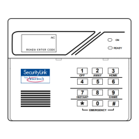
    Why is the "AC POWER" light off on my AMERITECH SecurityLink AM100 Security System?
    • B
      Bryan MarshallAug 19, 2025
      The AC power light may be off because of an interrupted AC power supply. Check the transformer connection and the powerline circuit breaker.
  • S
    scottstevenAug 21, 2025
    What to do if my AMERITECH Security System keypad beeps periodically?
    • C
      Courtney LeonAug 22, 2025
      Periodic beeping from the keypad can occur for several reasons: * The system is in TEST mode. To exit, enter "Code" + OFF. * A transmitter low battery has occurred and is displayed. Enter "Code" + OFF and replace the battery. * A supervision CHECK has occurred. Check the transmitter indicated and restore communication to the receiver to cancel the condition.
  • E
    Edward MooreAug 25, 2025
    How to troubleshoot an AMERITECH Security System intrusion alarm for no apparent reason?
    • R
      robertsnyderAug 25, 2025
      If you are getting intrusion alarms for no apparent reason on your AMERITECH Security System, consider the following: * A protected door or window may have been opened while the system was armed. Check with all occupants. * Improper user operation of exit/entry delays. Check the setting of entry and exit delays. * Magnets located too far from switches, and/or doors and windows not properly aligned. Check all openings for proper switch and magnet orientation.
  • A
    Amber CardenasAug 26, 2025
    How to fix AMERITECH Security System when it does not arm properly?
    • J
      jennifer00Aug 26, 2025
      If your AMERITECH Security System does not arm properly, it might be because the ready light is not on. Check for faulted zones and make them intact, or use Bypass arming if desired.
  • R
    Rebecca RichardsonAug 28, 2025
    What causes nuisance or phantom alarms in AMERITECH Security System?
    • J
      Joann CaldwellAug 28, 2025
      Nuisance or phantom alarms in your AMERITECH Security System could be caused by sensors not properly installed, wired, or monitored; check the installation to ensure it follows established procedures. Another cause might be a universal transmitter (5817) programmed incorrectly; check the programming switches on the transmitter.
  • T
    terrellmichaelSep 1, 2025
    Why is my AMERITECH SecurityLink AM100 Security System detector alarming for no apparent reason?
    • C
      Christine GreenSep 1, 2025
      If your AMERITECH Security System's detector is alarming for no apparent reason, it could be due to dust or dirt in the sensing chamber. Clean the unit's sensing chamber with a vacuum cleaner, following the unit's instructions. Another cause could be an improper location. Check the unit's instructions for locations to avoid and relocate the detector if necessary. The unit may also be malfunctioning, in which case, replace the detector.
  • C
    Christopher ThomasSep 3, 2025
    What does it mean when my AMERITECH Security System displays “CHECK” and a zone number?
    • T
      Tracy WilliamsSep 3, 2025
      The “CHECK” message along with a zone number (2–8) on your AMERITECH Security System indicates that the control has sensed a high resistance condition on a loop in one of the hard-wired zones. Check the sensor or the loop wiring in the affected zone. The system will not arm until this condition is corrected or the affected zone is bypassed.
  • G
    Gregory HardinSep 5, 2025
    What does it mean when the AMERITECH SecurityLink AM100 Security System transmitter zone number appears during Transmitter Sniffer mode, but does not clear?
    • L
      Lisa RangelSep 5, 2025
      If the transmitter zone number appears during Transmitter Sniffer mode on your AMERITECH Security System but does not clear, it could be due to a few reasons: * The transmitter zone type (ZT) is set to 00 (Not Used). Set the ZT to a valid active zone type in field 56. * The transmitter battery is not installed. Install the proper battery. * The 5800 System transmitter is not 'enrolled' in the system. "Enroll" the unit in field 56 or 83.
  • S
    Samuel BurnettSep 8, 2025
    What causes a low battery message on the keypad of my AMERITECH SecurityLink AM100?
    • R
      Richard BuchananSep 8, 2025
      A "Bat" or “System Lo Bat” message (without zone numbers), "Bat" or “Lo Bat” + "00," or "Bat" or “Lo Bat” + "nn" on your AMERITECH Security System keypad indicates that the system battery is low or missing.
  • H
    hardytimothySep 10, 2025
    Why doesn't my AMERITECH SecurityLink AM100 Security System respond to keystrokes on the keypad?
    • D
      dharrisSep 10, 2025
      If your AM100 AMERITECH Security System is not responding to keystrokes on the keypad, here are some possible reasons: * "CC" or "MODEM COMM" is displayed: The system is communicating with a downloader at the central station. Wait until the download session is finished. * "d1" or "Busy-Standby" is displayed: The system has just been powered on and is in its one-minute initialization. To bypass this time, press '#' + '0'. * "E4" or "E8" is displayed: More zones have been programmed than the zone expansion modules can handle. Delete some zones or use a higher capability RF receiver. * Keypad address setting is incorrect: Keypads must be set for address 31 (non-addressable mode).

Summary

RECOMMENDATIONS FOR PROPER PROTECTION

Smoke and Heat Detector Placement

Guidance on optimal placement of smoke/heat detectors for effective fire detection.

Intrusion Detection Sensor Placement

Recommendations for positioning intrusion sensors at entry points for coverage.

Manual Conventions and Symbols

Understanding Manual Conventions

Explains symbols, icons, and formatting used in the manual.

Section 1. GENERAL DESCRIPTION

Basic Hardwired Zones Overview

Details characteristics of the 8 basic hardwired zones, including supervision and response.

Expansion Zone Capabilities

Covers wired and wireless expansion zones, detailing supported modules and zone counts.

Remote Keypad Support

Lists compatible keypad models and their features for system interaction.

Section 1. GENERAL DESCRIPTION (Continued)

System Security Codes Explained

Details installer, master, babysitter, and duress codes for system access.

Zone Monitoring and Features

Covers zone monitoring, output relays, phone module, and paging capabilities.

Section 1. GENERAL DESCRIPTION (Continued)

Long Range Radio, Line Monitoring, and Programming

Details long range radio, line monitoring, programming, and power supply.

Back-Up Battery Requirements

Specifies the minimum required backup battery size and type.

Section 2. INSTALLING THE CONTROL

Control Cabinet Mounting and Lock Installation

Instructions for securely mounting the control cabinet and installing the lock.

Section 2. INSTALLING THE CONTROL (Continued)

Mounting Control and RF Receiver Boards

Steps for mounting the main circuit board and RF receiver.

Section 2. INSTALLING THE CONTROL (Continued)

Standard Phone Line Connections Wiring

Details wiring for standard telephone line connections.

AC Transformer Wiring Instructions

Guides for wiring 1321 and 4300 transformers.

Section 2. INSTALLING THE CONTROL (Continued)

Back-Up Battery and Earth Ground Connections

Steps for connecting the backup battery and earth ground.

Section 3. INSTALLING REMOTE KEYPADS

Keypad Models and Wiring Guidelines

Lists compatible keypads and provides wiring charts and guidance.

Section 3. INSTALLING REMOTE KEYPADS (Continued)

Keypad Mounting and Supplementary Power

Instructions for mounting keypads and using extra power supplies.

Section 3. INSTALLING REMOTE KEYPADS (Continued)

Preliminary System Check-Out Procedure

Steps to verify system readiness before full wiring.

Section 4. BASIC HARD-WIRED ZONES 1-8

Hardwired Zone Characteristics and Wiring

Details zone features like EOLR supervision and wiring for burglary devices.

Section 4. BASIC HARD-WIRED ZONES 1-8 (Continued)

Smoke Detector Wiring Instructions

Specific instructions for wiring 2-wire smoke and 4-wire smoke/combustion detectors.

Section 4. BASIC HARD-WIRED ZONES 1-8 (Continued)

2-Wire Latching Glass Break Detector Wiring

Instructions for connecting 2-wire latching glass break detectors on zone 8.

Section 4. BASIC HARD-WIRED ZONES 1-8 (Continued)

Hardwired Zone Programming and Check-Out

Steps for programming zones and verifying their operation.

Section 5. WIRED ZONE EXPANSION (4219, 4229)

Installing Wired Zone Expansion Modules

Information on adding expansion modules like 4219 and 4229.

Section 5. WIRED ZONE EXPANSION (Continued)

Wired Expansion Zone Check-Out Procedure

Steps to test wired expansion zones after installation.

Section 6. WIRELESS EXPANSION (5800 SYSTEM)

Wireless System Overview and Receiver Setup

General info on wireless zones, receiver supervision, and house ID.

Section 6. WIRELESS EXPANSION (Continued)

5881;5882 RF Receiver Installation and Setup

Detailed steps for installing and configuring the RF receiver.

Section 6. WIRELESS EXPANSION (Continued)

5800 TM Module Installation and Transmitter Basics

Installing the 5800TM module and general transmitter information.

Section 6. WIRELESS EXPANSION (Continued)

Transmitter Types, Battery Life, and Sniffer Mode

Details transmitter types, battery expectations, and the sniffer mode test.

Section 6. WIRELESS EXPANSION (Continued)

5800 Series Transmitter Model Details

A table listing transmitter models, input types, and special notes.

Section 6. WIRELESS EXPANSION (Continued)

Transmitter Installation Testing and DIP Switch Settings

Performing Go/No Go tests and setting DIP switches for 5827 transmitters.

Section 7. RELAY OUTPUTS & POWERLINE CARRIER DEVICES

Relay;PLC Device Basics and Module Setup

Explains relay/PLC functions, programming, and setup for 4204/4229 modules.

Section 7. RELAY OUTPUTS & POWERLINE CARRIER DEVICES (Continued)

Powerline Carrier Devices and Transformer Use

Details Powerline Carrier device functionality and the need for a 4300 transformer.

Section 7. RELAY OUTPUTS & POWERLINE CARRIER DEVICES (Continued)

4300 Transformer Wiring and Relay Output Programming

Wiring the 4300 transformer and programming relay actions.

Section 8. 4285 & 4286 VIP PHONE MODULES

Phone Module Functionality and Mounting

Overview of phone module capabilities and instructions for mounting.

Section 8. 4285 & 4286 VIP PHONE MODULES (Continued)

Phone Module Wiring and Caller ID Integration

Details phone module wiring and connecting Caller ID units.

Section 8. 4285 & 4286 VIP PHONE MODULES (Continued)

Critical Phone Module Wiring Notes

Important wiring notes and diagrams for the phone module.

Section 8. 4285 & 4286 VIP PHONE MODULES (Continued)

Phone Module Programming and Operation Check

Steps for programming and testing the phone module's functionality.

Section 9. EXTERNAL SOUNDERS

Compatible Sounder Models and UL Notes

Lists compatible sounders and important UL installation notes.

Section 9. EXTERNAL SOUNDERS (Continued)

Sounder Wiring Connections and Testing

Instructions for connecting sounders and performing tests.

Section 10. LONG RANGE RADIO

Long Range Radio Functionality and Connection

Explains long range radio use and details its wiring.

Section 11. REMOTE KEYSWITCH

Keyswitch Installation and Connection Procedures

Steps for installing and wiring the remote keyswitch.

Section 11. REMOTE KEYSWITCH (Continued)

Keyswitch Wiring Diagrams

Wiring diagrams for keyswitch installation with/without 4300 transformer.

Section 11. REMOTE KEYSWITCH (Continued)

Programming the Remote Keyswitch Functionality

Instructions for programming zone 7 for keyswitch operation.

Section 11. REMOTE KEYSWITCH (Continued)

Keyswitch Operation and LED Indicators

Explains how to use the keyswitch and interpret LED status.

Section 12. AUDIO ALARM VERIFICATION (AAV) UNIT

AAV Unit Purpose and Wiring Information

Explains AAV for voice dialog and provides wiring guidance.

Section 12. AUDIO ALARM VERIFICATION (AAV) UNIT (Continued)

AAV Unit Wiring Diagrams

Diagrams for connecting AAV with and without a phone module.

Section 13. FINAL POWER UP

Earth Ground, AC Power-Up, and Battery Sizing

Steps for final power-up, including grounding, AC connection, and battery calculation.

Section 13. FINAL POWER UP (Continued)

Making Battery Connections and Current Draw Worksheet

Instructions for connecting the battery and a worksheet for current draw.

Section 14. MECHANICS OF PROGRAMMING

General Programming Information and Data Fields

Overview of programming modes, data storage, and entering data fields.

Section 14. MECHANICS OF PROGRAMMING (Continued)

Interactive Programming Modes and Defaults

Details interactive modes (✱56, ✱80, etc.), loading defaults, and exiting programming.

Section 15. ZONE RESPONSE TYPE DEFINITIONS

Zone Type Overview and Definitions

Explains zone types and lists definitions for various types (00-24).

Section 16. DATA FIELD DESCRIPTIONS

Installer Code and RF System Configuration

Fields ✱20 (Installer Code), ✱22 (RF System), ✱24 (RF House ID).

Zone Expansion and Chime Configuration

Fields ✱25 (Wired Zone Expansion), ✱26 (Chime by Zone).

Section 16. DATA FIELD DESCRIPTIONS (Continued)

Communication and Sounder Setup Fields

Fields ✱27 (Powerline Carrier ID), ✱29 (LRR Output), ✱30 (Keyswitch), ✱32 (Fire Sounder Timeout).

Phone Module and Alarm Sounding Fields

Fields ✱28 (Phone Module Code), ✱31 (Single Alarm Sounding).

Section 16. DATA FIELD DESCRIPTIONS (Continued)

Alarm Timing and Exit;Entry Delay Configuration

Fields ✱33-✱36 for alarm timing and entry/exit delays.

Arming Confirmation and Power-Up State Fields

Fields ✱37-✱39 for arming warnings, dings, and power-up state.

Section 16. DATA FIELD DESCRIPTIONS (Continued)

Dialer, Phone, and Account Number Fields

Fields ✱40-✱44 for PABX, phone numbers, and account numbers.

Phone System and Report Format Fields

Fields ✱47 (Phone System Select), ✱48 (Report Format).

Section 16. DATA FIELD DESCRIPTIONS (Continued)

Split;Dual Reporting Configuration Field

Description for field ✱49 regarding split/dual reporting.

Section 16. DATA FIELD DESCRIPTIONS (Continued)

Dialer Delay and Report Format Selection Fields

Fields ✱50 (Dialer Delay), ✱51 (Periodic Test), ✱52 (Test Offset), ✱53 (SESCOA/RADIONICS).

Section 16. DATA FIELD DESCRIPTIONS (Continued)

System Status and Trouble Report Codes

Fields ✱59-✱67 for various system status and report codes.

Section 16. DATA FIELD DESCRIPTIONS (Continued)

Restore Report Codes and Pager Configuration

Fields ✱68-✱76 and ✱88, ✱89 for restore codes and pager setup.

Section 16. DATA FIELD DESCRIPTIONS (Continued)

Event Logging and Option Selection Fields

Fields ✱90 (Event Logging), ✱91 (Option Selection), ✱92 (Phone Line Monitor), ✱93 (Number of Reports).

Section 16. DATA FIELD DESCRIPTIONS (Continued)

Download and Programming Command References

Fields ✱94, ✱95 and programming commands ✱56, ✱80, etc.

Section 17. ZONE PROGRAMMING (✱56 Menu Mode)

Zone Programming Overview and Program Tool Usage

Introduction to zone programming and using transmitters as tools.

Section 17. ZONE PROGRAMMING (Continued)

Zone Type, Report Code, and Input Device Assignment

Assigning zone types, report codes, and input device types.

Section 17. ZONE PROGRAMMING (Continued)

Transmitter Serial Number Enrollment Procedures

Procedures for entering loop numbers and learning transmitter serial numbers.

Section 17. ZONE PROGRAMMING (Continued)

Transmitter Enrollment Confirmation and Alpha Descriptors

Confirming enrollment and prompting for alpha descriptors.

Section 18. OUTPUT DEVICES (✱80 Menu Mode)

Output Device Programming Options Defined

Defines ACTION and START programming for output devices.

Section 18. OUTPUT DEVICES (Continued)

STOP Programming Options for Devices

Explains STOP programming options for de-activating devices.

Section 18. OUTPUT DEVICES (Continued)

Programming Relays, PLC Devices, and Zone Choices

Steps for programming devices and lists of zone/system operation choices.

Section 18. OUTPUT DEVICES (Continued)

Example Output Device Programming Scenario

A practical example demonstrating output device programming.

Section 19. ZONE LISTS (✱ 81 Menu Mode)

Zone List Programming and Management

Instructions for creating, deleting, and managing zone lists.

Section 20. ALPHA DESCRIPTOR PROGRAMMING

Zone Descriptor Programming Overview

Explains programming user-friendly zone descriptions.

Section 20. ALPHA DESCRIPTOR PROGRAMMING (Continued)

Zone Descriptor Summary Mode Display

How programmed zone descriptors are displayed.

Section 20. ALPHA DESCRIPTOR PROGRAMMING (Continued)

Saving Zone Descriptors and Exiting Mode

Steps for saving descriptors and exiting the programming mode.

Section 20. ALPHA DESCRIPTOR PROGRAMMING (Continued)

Adding Custom Words to Vocabulary

Procedure for adding custom words for zone descriptors.

Section 20. ALPHA DESCRIPTOR PROGRAMMING (Continued)

Alpha Vocabulary List and Character Chart

Reference lists for words and characters used in descriptors.

Section 21. USING ✱83 SEQUENTIAL MODE

Sequential Transmitter Enrollment Process

Steps for sequentially enrolling wireless transmitters.

Section 21. USING ✱83 SEQUENTIAL MODE (Continued)

Learning and Confirming Transmitter Serial Numbers

Procedures for learning and confirming transmitter serial numbers.

Section 21. USING ✱83 SEQUENTIAL MODE (Continued)

Finalizing Transmitter Enrollment

Completing the enrollment process and exiting the mode.

Section 22. REMOTE PROGRAMMING AND CONTROL (DOWNLOADING)

Remote Programming Overview and Equipment Needs

Information on remote programming capabilities and required equipment.

Section 22. REMOTE PROGRAMMING AND CONTROL (Continued)

Remote Programming Operations and Advisory Notes

Details on remote functions and important advisory notes.

Section 23. SYSTEM COMMUNICATION

Report Code Formats and Transmission Process

Explains communication formats and the handshake/kissoff process.

Section 23. SYSTEM COMMUNICATION (Continued)

Details of Standard, Expanded, and 4+2 Report Formats

In-depth explanations of various report format structures.

Section 23. SYSTEM COMMUNICATION (Continued)

Ademco Contact ID Event Codes Table

A list of Contact ID event codes and their meanings.

Section 24. SYSTEM OPERATION

Security Code Management

Explains installer, master, and secondary user codes.

Section 24. SYSTEM OPERATION (Continued)

Keypad Functions and Arming Commands

Details keypad operations, arming modes, and system commands.

Section 24. SYSTEM OPERATION (Continued)

Arming Modes Summary and Exit Error Displays

Summarizes arming modes and explains exit error alarm displays.

Section 24. SYSTEM OPERATION (Continued)

Understanding Trouble Conditions and System Displays

Explains common trouble messages and other system status displays.

Section 25. TESTING THE SYSTEM

System Test Procedures

Step-by-step instructions for testing the entire security system.

Section 25. TESTING THE SYSTEM (Continued)

Transmitter Testing Modes and Installer Guidance

Testing wireless transmitters and installer responsibilities.

Section 26. TROUBLESHOOTING GUIDE

Troubleshooting Wireless System Issues

A table addressing common wireless system symptoms and causes.

Section 26. TROUBLESHOOTING GUIDE (Continued)

Troubleshooting Control and Smoke Detector Issues

A table addressing control and smoke detector problems.

Technical Support Preparation

Pre-Call Checklist for Technical Support

Steps to take before contacting technical support for assistance.

REGULATORY AGENCY STATEMENTS

FCC Part 15 and Part 68 Compliance Statements

FCC statements regarding radio frequency energy and telephone connections.

Section 27. SPECIFICATIONS & ACCESSORIES

AM100 Control and AM6128 Keypad Specifications

Technical specifications for the main control unit and keypad.

Section 27. SPECIFICATIONS & ACCESSORIES (Continued)

Specifications for Keypads, Receivers, Modules, and Phones

Technical specifications for various system components.

Section 27. SPECIFICATIONS & ACCESSORIES (Continued)

Compatible Accessories and Detector Specifications

Lists compatible accessories and specifications for smoke/combustion detectors.

APPENDIX A. 5800 RF System Wireless Transmitters

Transmitter Input Loop Identification Guide

Identifies input loops for 5800 series wireless transmitters.

WARNING: SYSTEM LIMITATIONS

Understanding Alarm System Limitations and Risks

Details potential failure points and limitations of the alarm system.

ADEMCO LIMITED WARRANTY

Warranty Terms and Conditions

Outlines the seller's obligations and limitations for product warranty.

AMERITECH SecurityLink AM100 Specifications

General IconGeneral
TypeWireless Security System
Battery BackupYes
CommunicationCellular
Wireless Frequency319.5 MHz
Power SupplyAC Adapter
Zones8

Related product manuals