11
The Generation I board does NOT have the 24V bias point for the 100K resistor. In these amplifiers the 100K 2-
watt resistor goes from anyplace on the filament system to chassis ground.
Gen II board:
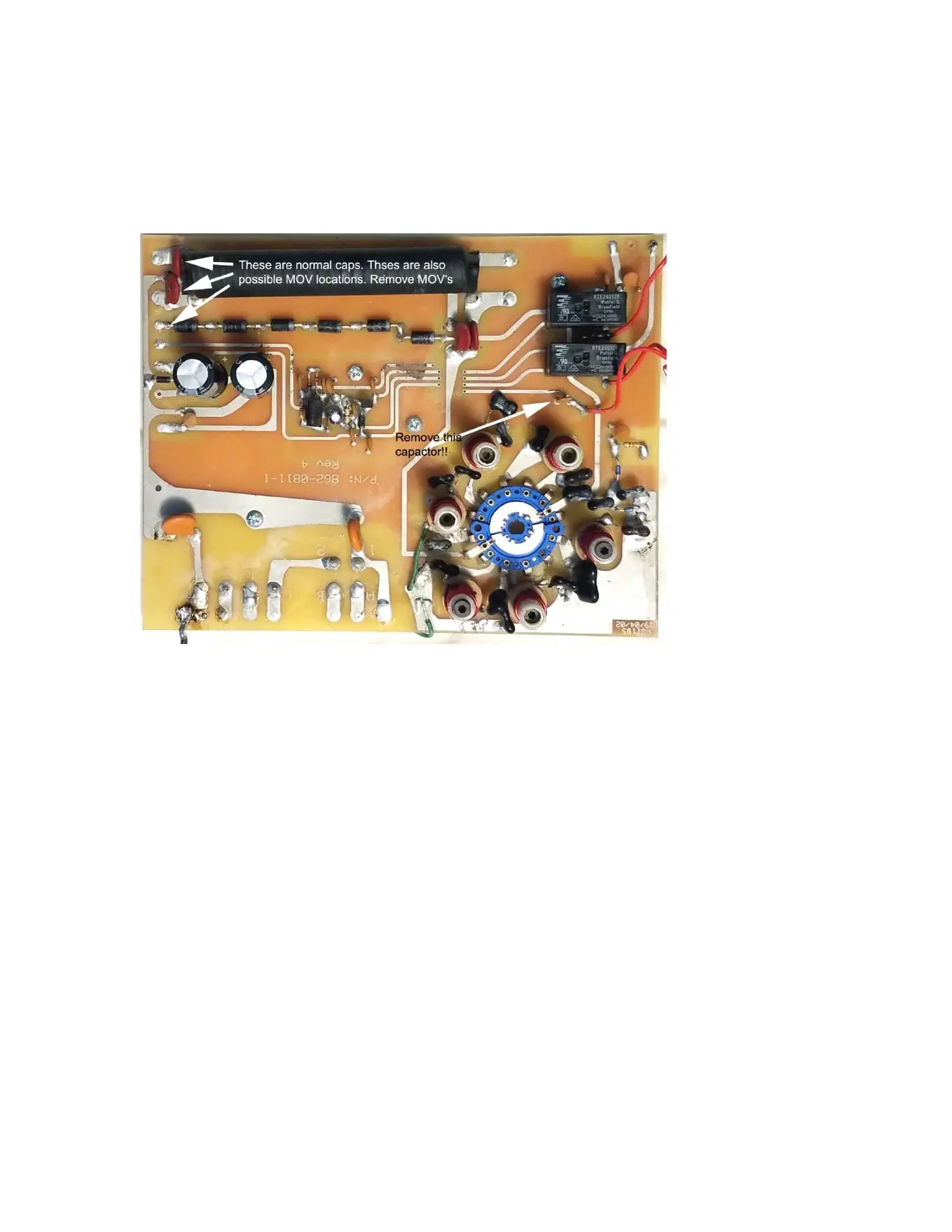
Look for the small capacitor near dual relays (Fig. 13) and remove it, if installed. The string of 6 large forward
connected rectifier diodes adds about 4 volts of bias.
Figure 13 Gen II input board
Gen III board around 2012
This board das GDT pads and does not have the problem relay line capacitor near the relays.
Note: this generation is after I recommended omitting all MOVs. Production boards may or may not have
MOVs