12
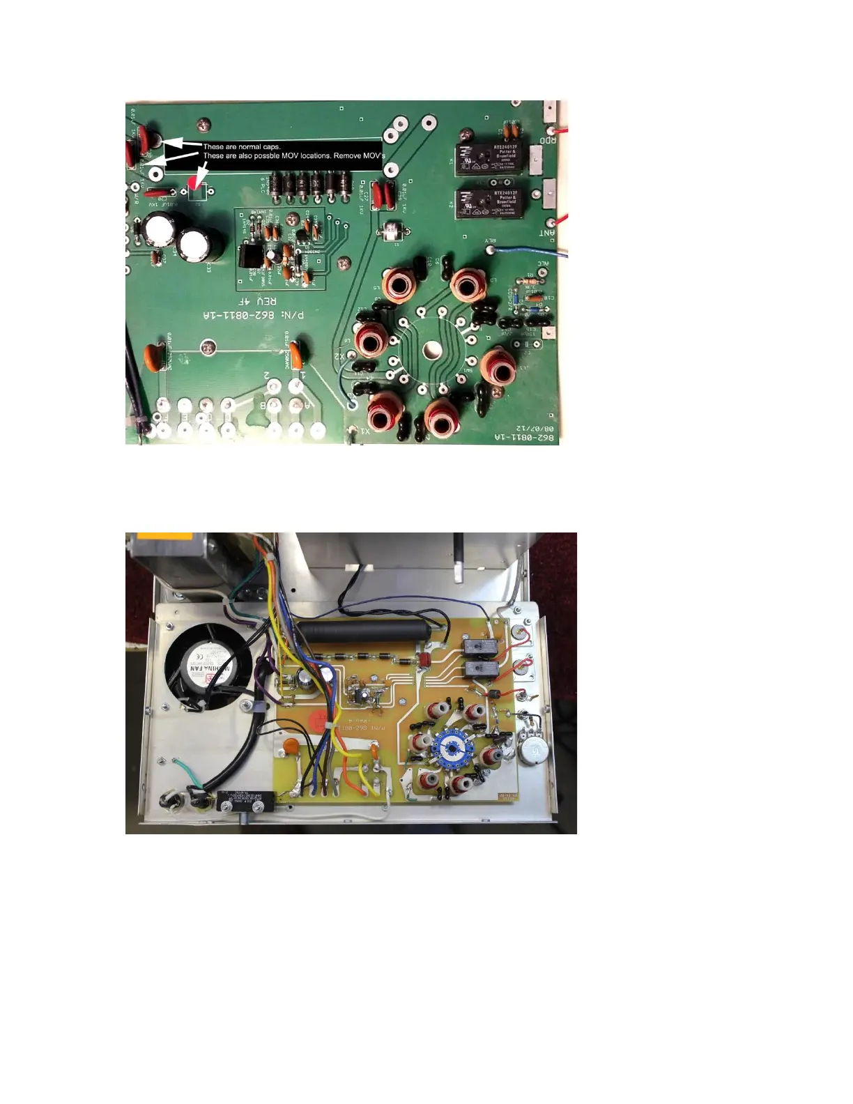
Figure 14 Gen III and later input boards
This is the ideal working position for all back panels. This is a correctly wired back panel. The back panel easily
slips backwards off the switch drive without any wire removal. This is a two-relay board (the two black relays
to the right side). Notice the string of rectifier diodes used for bias running along the black filament choke.
Figure 15 All units rear panel down
The rear of the input switch shaft is exposed. The sharp rear shaft edges should be filed or sanded to break the
edge into a taper or radius. This significantly helps when slipping the shaft back into the rear switch. A few
minutes tapering the edges can prevent switch damage and prevent expensive broken switches.
 Loading...