19
A01-00104 Rev A
Display Functionality
The location should provide adequate airflow around the UPM. Pro-
vide a minimum 3” clearance on all sides for proper ventilation.
Applying Power to the UPM
Connect the power cord to a verified grounded 3 wire receptacle. Verify
that the Site Wiring Fault “SF” is off (120 VAC models only). Once properly
connected and initially checked, turn on the UPM by pressing and holding the
front panel On/Off switch for 3 seconds.
Operational Tests
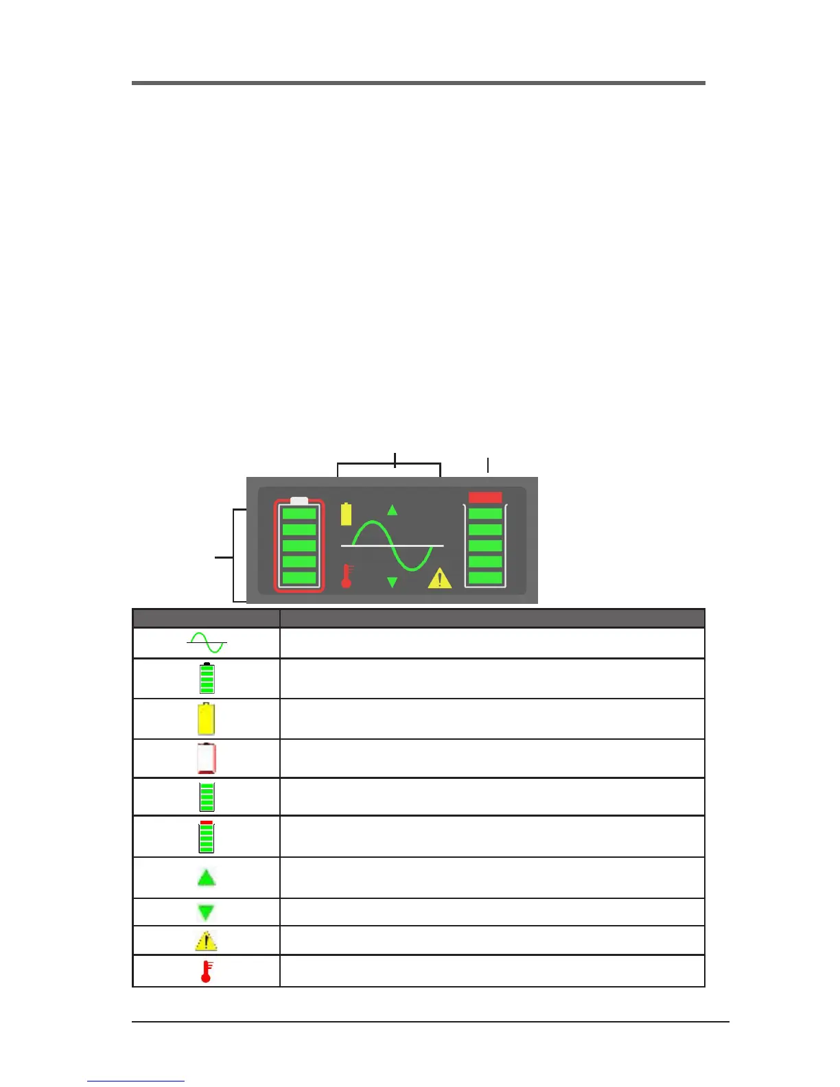
Observe the front panel of the UPM. The following table shows system status
behavior.
UPM LED DISPLAY UNIT STATUS
UPM output on
Battery charge status in 20% increments
UPM in battery operation due to improper incoming AC voltage
Battery fault or battery disconnected
UPM load status in 20% increments
UPM overloaded
Unit in buck operation due to high incoming AC voltage
Unit in boost operation due to low incoming AC voltage
Fault
UPM over temperature
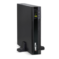
UPM Front Panel
Output
Battery
System Status
 Loading...