14 05/18/2021
193111-121
INSTALLATION
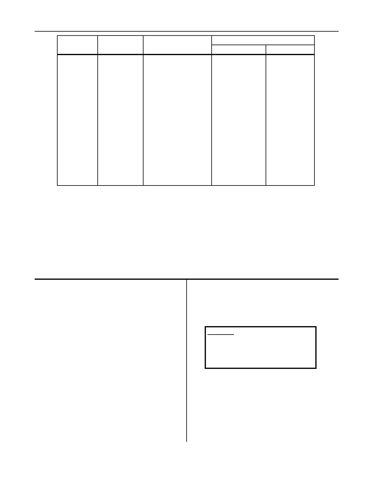
Table 4-1 Recommended AC Input and Branch Fusing
LINE AMPS
DISCONNECT
SWITCH *
COPPER CABLE SIZE AWG * *
BRANCH FUSE SIZE
(AMPERES) POWER GROUND
0-2.5 30A 5 No. 14 No. 14
2.6-4.5 30A 7 No. 14 No. 14
4.6-7.5 30A 10 No. 14 No. 14
7.6-12 30A 15 No. 14 No. 14
12.1-16 30A 20 No. 12 No. 12
16.1-18 30A 25 No. 10 No. 10
18.1-22 30A 30 No. 10 No. 10
22.1-24.5 60A 35 No. 8 No. 10
24.6-32.5 60A 40 No. 8 No. 10
32.6-40 60A 50 No. 8 No. 10
40.1-45 60A 60 No. 6 No. 10
45.1-57.5 100A 80 No. 4 No. 8
57.6-78 100A 100 No. 2 No. 8
78.1-102.5 200A 125 No. 2 No. 6
102.6-135 200A 150 No. 1/0 No. 6
The above table (Table 4-1) is based on 75°C (167°F) rated conductors and 40°C (104°F) ambient temperatures.
Refer to National Electrical Code (2008) Tables 310-16 corrected to 40°C (104°F).
* For 115, 208, and 230-volt lines, use 250-volt disconnect switch.
For 440-480, 575-volt lines, use 600-volt disconnect switch.
* * Two conductors and ground conductor required for single phase.
Three conductors and ground conductor required for three phase.
Recommended minimum size of grounding conductors (based on National Electrical Code 2008 – Table 250-95).
Line Connections to Battery Charger
Follow local code requirements if different than
instructions in this manual.
1. Turn charger OFF.
2. Be sure charger is connected correctly for available
line voltage as instructed above.
3. On charger nameplate, note the AC input amperes
corresponding to the line voltage to which charger
is to be connected. Use that ampere value to select
the proper disconnect switch, fuse, and power cable
sizes from Table 4-1.
4. Route AC power input cable in through knockout
provided in side panel of charger cabinet. Securely
fasten cable wires to a power input terminal inside
charger. Refer to Grounding section of this manual
for proper connection of grounding conductor.
(The lower access panel will have to be removed to
provide access to terminal block.)
5. With disconnect switch (on AC input power line)
in “OPEN” or “OFF” position, connect power
cable coming from charger, to the switch. Install
fuses in switch.
AC Supply Input Conditions:
Supply voltage should not exceed +/-10% of rated
input voltage value. Consistent power should
be provided with fluctuations not to exceed
1200VAC 850Vrms) for a duration longer than 25
microseconds.
WARNING
At all times, safety must be considered
an important factor in the installation,
servicing and operation of the product
and skilled, qualified technical assis-
tance should be utilized.