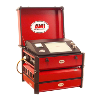
MODEL 227
OPERATION MANUAL
Doc # 740063 Rev E
SECTION V - OPERATION
5.1 INITIAL POWER ON/STATUS SCREEN
4. (continued)
UPPER SCREEN
TO WELD PRESS LIB TO PROGRAM PRESS PRO
SYS HOURS - 00000.0
ARC HOURS - 00000.0
LOWER SCREEN
TEMP-OK INPUTAC-OK GAS-OK LVPS-OK
COOL-OK SENSOR1-OK 2-OK 3-OK
Actual hours will appear where the above show 0. COOL, GAS or
SENSOR 1,2,3 may indicate FLT where OK appears. This is considered
normal at power-up.
5.2 USE OF NEXT/PREV SCREENS/LEVELS
Weld schedules contain more data than can be shown at one time. To display this
data the NEXT/PREV SCREEN keys and NEXT/PREV LEVEL keys must be
used. These keys are located at the corners of the lower display. When there is
more data on another screen or level, a flashing * will appear in the appropriate
corner (s) to indicate that more information is available.
Screen/Level keys are used in selection of a weld schedule and all weld schedules
use 8 basic Lower Screen Displays that appear in the following order:
1. PROMPT SCREEN
= Appears when a weld schedule is called up from
memory. Gives instructions in lower display and shows Library Description,
Weld Mode and Fault Status in upper display.
2. LEVEL 01 AMPS - TIME - PULSE = Displays the value of Amps, Level
Time and Pulse Times for Level 1.
3. LEVEL 01 RPM/IPM - MODES = Displays the value of Travel Speeds,
Travel Mode and Pulse Mode for Level 1.
4. LEVEL 01 WIRE -AVC-AVC MODE = Displays the value of Wire Feed
Speeds, AVC settings and AVC MODE for Level 1.
5. LEVEL 01 OSC
= Displays the value of Osc Amplitude, IN Dwell, Out
Dwell and Excursion times for Level 1.
5.2