Model 415
Operation Manual
3. The Weld Current calibration schedule will be run in WELD
Mode and will contain the following:
Onelevel Functions
Prepurge 10 Torch Gas Rate 40*
Upslope 1.0 Start Level 25
Num Starts 1
Postpurge 20 Level Advance Manual
Downslope 5.0 Stubout Mode On*
Start Mode Touch*
Multilevel Level 1 Functions
Pri Amps 200 Bck Pulse
10.0
Bck Amps 200 Pulse Mode OFF
Pri Pulse 10.0 Travel Step OFF
Multilevel Level 2 Functions
Pri Amps 400* Bck Pulse
10.0
Bck Amps 400* Pulse Mode OFF
Pri Pulse 10.0 Travel Step OFF
*Maximum torch value of 300 amps – use 300 amps here. Step 5.6-6-9 value would then be
3.75 VDC +/- 0.037 VDC.
4. Level Time will be in the Manual Mode requiring the operator to Sequence stop the M-415
after measurements and any required adjustments are done. Pulse Mode should be OFF so
only the Primary Current Amps is checked. The Primary Amps should be set to 200 for the
Initial measurement. Insure that the Travel Mode switch is set to OFF. It is very important
the calibration measurements are done quickly, so not to melt the work piece. A suggestion
is to make the necessary connections to the PCB test points and disconnect the test
leads at the DMM until an arc is established.
5. Recall from the LIBRARY the appropriate Calibration Weld Schedule.
6. CURRENT CALIBRATION WITHOUT EXTERNAL SHUNT
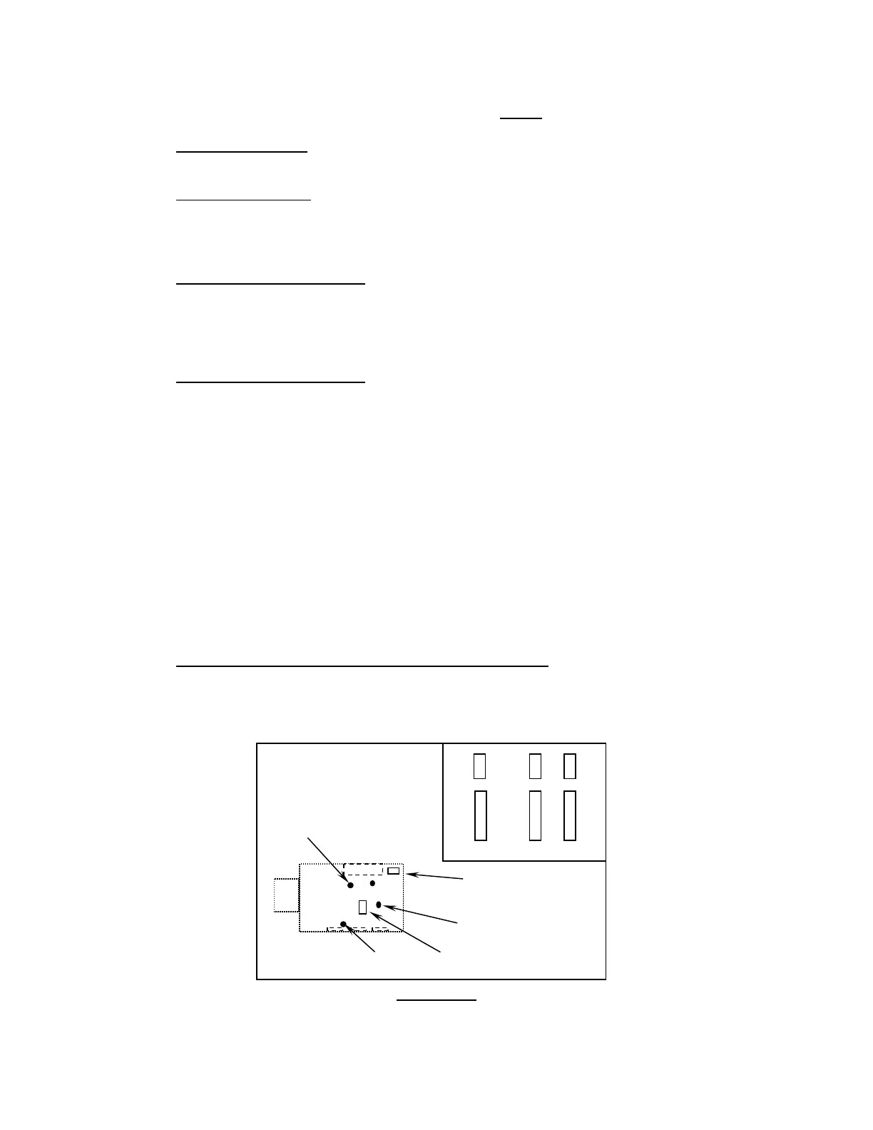
1. Connect the negative test lead to TP-2 and the positive test lead to TP-1 of the weld
current servo. The Current Servo (P/N 13D150300-01) can be accessed through an
opening in the upper deck plate just below the Interface PCB.
TP-1
R-39 DO NOT ADJUST
FACTORY PRESET
INTERFACE A 0/1 B 0/1
TP-2
TP-3
R36
DIAGRAM 3
Docum
e
nt No. 740084
Revision N
33