Model 415
Operation Manual
5.7 ARC VOLTAGE CONTROL (AVC) CALIBRATION
NOTE
A weld schedule is required for the following calibration. The first time a calibration is done it will be
necessary to CREATE a Calibration Weld Schedule. This section will outline all pertinent schedule
elements needed. (Pass 2)
1. Insure that a Weld Head with AVC is connected per section III of the M415 Operation Manual.
NOTE
A weld schedule is required for the following calibration. The first time a calibration is done it will be
necessary to CREATE a Calibration Weld Schedule. This section will outline all pertinent schedule
elements needed. (Pass 2)
2. Insure that a Weld Head with AVC is connected per section III of the M415 Operation Manual.
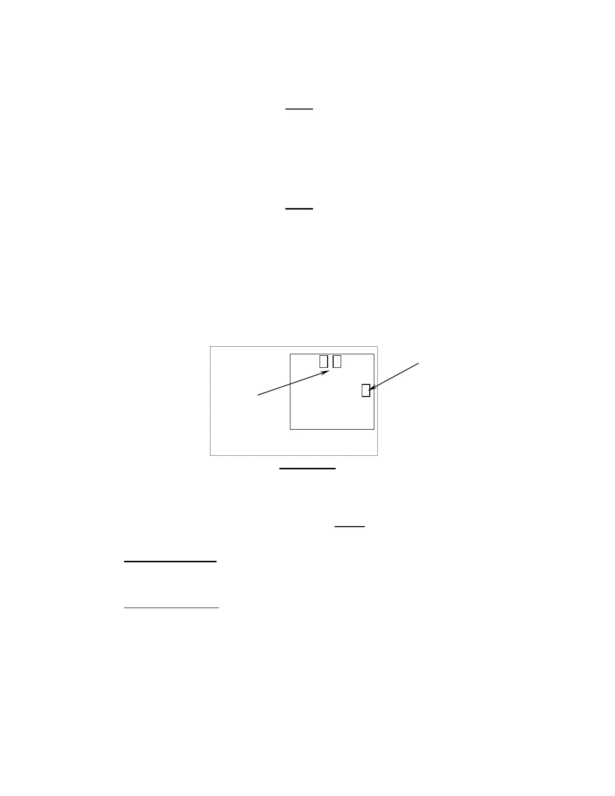
3. The AVC Calibration is done on the AVC / OSC PCB (P/N 13D150313-01) located on the Servo
PCB mounting plate in labeled slot B 0/1. Locate the AVC adjustment trim pot R-40 on the
PCB (diagram 4). DO NOT ADJUST TRIM POTS R-80 AND R-81 (these are factory calibrated
for use with special application weld heads or fixtures not discussed in this section).
R-40
R-80 & R-81
DIAGRAM 4
4. To calibrate the AVC the user will need to have a Weld Schedule in the Library for the M-415
and applicable Weld Head, (Pass 2).
5. The AVC calibration schedule will be run in the WELD
Mode and will contain the following:
Onelevel Functions
Prepurge 010 Torch Gas Rate 20
Upslope 01.0 Start Level 25
AVC Start Delay 1.0 Num Starts 1
Level Advance Manual
Postpurge 010 Stubout Mode On
Downslope 05.0 Start Mode Touch
AVC Stop Delay 1.0 AVC Resp 15**
Osc Mode OFF
**Note: For M-415 Software Revisions prior to Rev. 1.43, use an AVC Response of five (5) in
place of the pictured AVC Resp 15.
Docum
e
nt No. 740084
Revision N
35