17
INSTALLATION
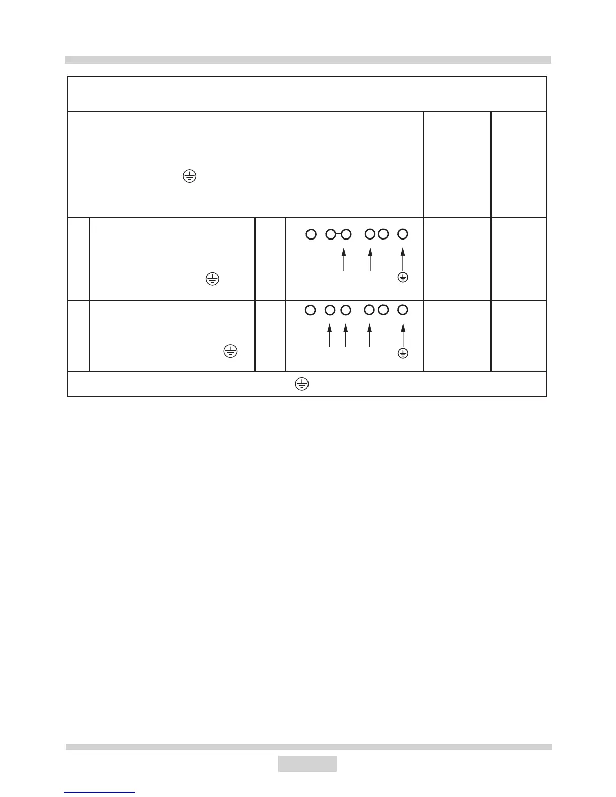
WIRING DIAGRAM
Important! Heating elements operate at 230V.
Important! For each connection the protective conductor must be connected
to the terminal marked .
Type /
Conductor
cross sec-
tion
Fuse
protec-
tion
1 For a 230 V single phase connec-
tion with a neutral lead, terminals
L1, L2 are bridged, neutral lead is
connected to terminal N, and the
protective conductor to .
1N~
HO5VV-FG
3X 4 mm
2
min.30 A
2* For a 230/400 V two phase con-
nection with a neutral lead, neutral
lead is connected to terminal N, and
the protective conductor to .
2N~
HO5VV-FG
4X2,5mm
2
min.16 A
L1=R, L2=S, L3=T; N = neutral lead connection; = protective lead terminal
* For domestic 3-phase 230/400 V electrical system, connect the remaining wire to the
terminal:L3, which is not connected to the hob internal electrical system.
* NN terminals are internally connected, they need not be bridged
L1
N
L1L2
N
 Loading...