AMP RESEARCH POWER STEP – GMC / CHEVROLET
4
5
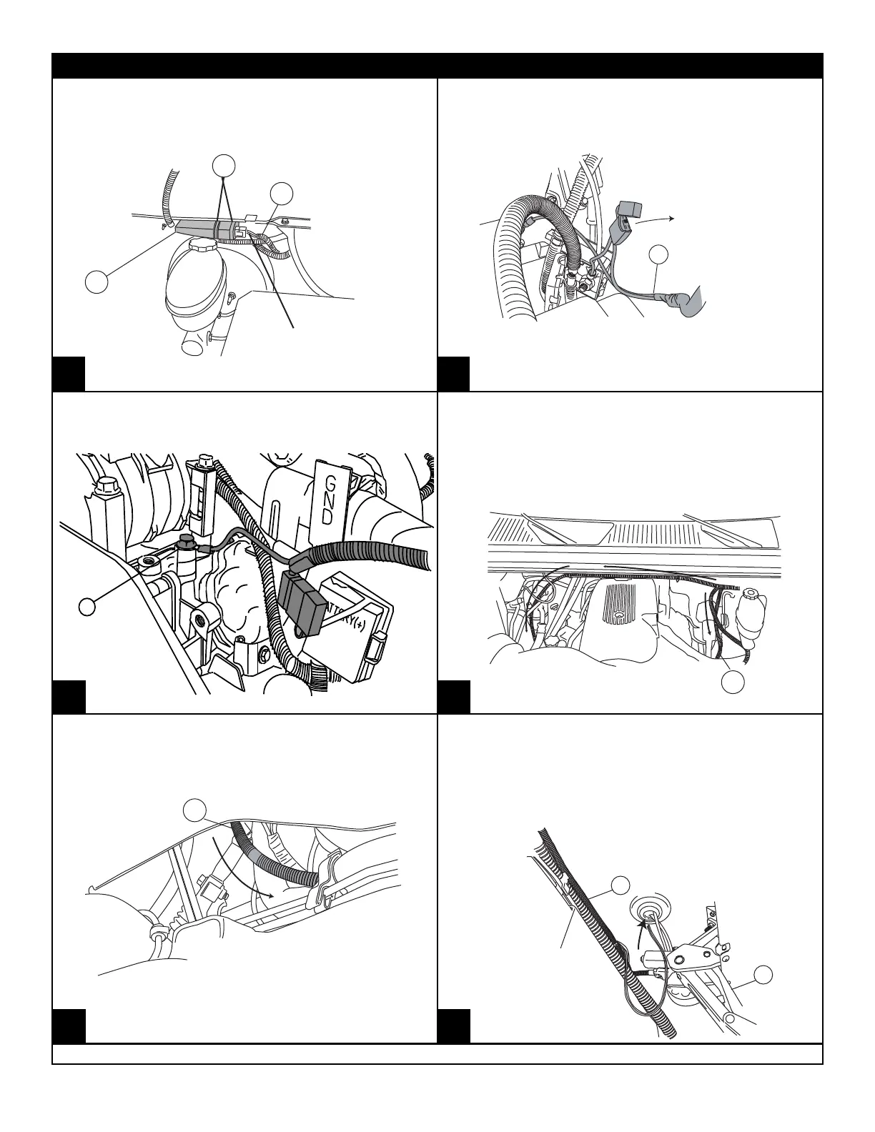
Using the two 11” cable ties, mount controller to
factory wire conduit above brake booster on
drivers side of truck.
Plug in wire harness.
(Ensure that locking
tabs engage.)
15
4
Route long end of wire harness above engine
and down through passenger side wheel well.
Zip tie harness to cowling clips on fire wall.
Route short end down drivers side.
Secure with zip ties.
4
Route wire harness along the frame. Secure
with zip ties.
4
3
Poke hole through rubber grommet near
front door on underside of floor panel with
small phillips screwdriver. Push both wires
through hole.
(See Step 20 for passenger side notes.)
Plug wire
harness into
motors.
Remove power fuse. Attach power lead RED wire
to positive lead in the junction box. CAUTION:
Do not ground wrench when engaged with nut.
Attach ground lead to junction box mount-
ing bracket. (See Step 15 for Diesel Engine
grounding location)
Diesel Models only! Using supplied Hex Head
Screw connect ground to air compressor mount-
ing bracket.
16
17
16
13 14
18
17
15
13
www.amp-research.com
7/11
INSTALLATION GUIDE
IM75113 rev 04.28.11
www.amp-research.com
7/11
INSTALLATION GUIDE