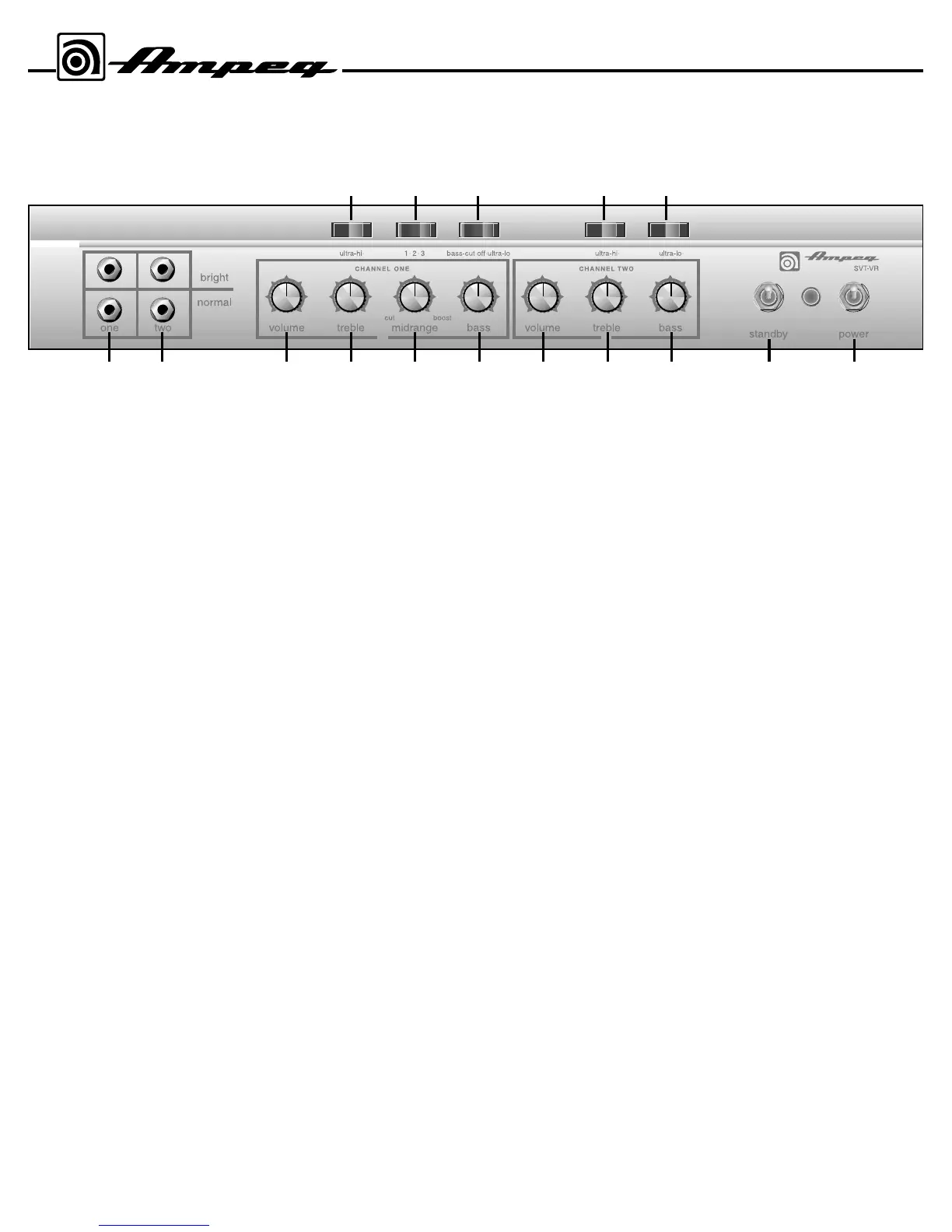
1. ONE: (The Channel One Input jacks) The signal output from an instru-
ment or a line level signal may be connected here by means of a shielded
instrument cable. Either the Bright or Normal jack may be used - the Bright
jack enhances the high frequencies of the input signal. The signal at these
jacks is sent into the Channel One preamp section (tone and volume con-
trols).
2. TWO: (The Channel Two Input jacks) The signal output from an instru-
ment or a line level signal may be connected here by means of a shielded
instrument cable. Either the Bright or Normal jack may be used - the Bright
jack enhances the high frequencies of the input signal. The signal at these
jacks is sent into the Channel Two preamp section (tone and volume con-
trols).
3. VOLUME: Use this control to adjust the output level of Channel One.
4. TREBLE: Use this control to adjust the high frequency level of the sig-
nal of Channel One. This control provides 12dB of cut or boost at 4kHz.
The high frequency output is flat at the center position.
5. MIDRANGE: Use this control to adjust the mid frequency level of the
signal of Channel One. This control provides 20dB of cut or boost at the
frequency selected by the 1•2•3 switch (#8). The midrange frequency out-
put is flat at the center position.
6. BASS: Use this control to adjust the low frequency level of the signal of
Channel One. This control provides 12dB of cut or boost at 40Hz. The low
frequency output is flat at the center position.
7. ULTRA-HI: This switch increases the high frequency output of Channel
One. The Ultra Hi is active when the right side of the switch is depressed.
The amount of boost is dependent on the setting of the Volume control
(#3).
8. 1•2•3: This switch selects the frequency to be affected by the Midrange
control (#5). The available frequencies are 220Hz (left side of the switch
depressed), 800Hz (switch in the center position), or 3kHz (right side of the
switch depressed).
9. BASS-CUT/OFF/ULTRA-LO: Depressing the left side of this switch
decreases the low frequency output of Channel One. Depressing the right
side of this switch enhances the low frequency output of Channel One. The
switch is inactive in the center position.
10. VOLUME: Use this control to adjust the output level of Channel Two.
11. TREBLE: Use this control to adjust the high frequency level of the sig-
nal of Channel Two. This control provides 12dB of cut or boost at 4kHz.
The high frequency output is flat at the center position.
12. BASS: Use this control to adjust the low frequency level of the signal
of Channel Two. This control provides 12dB of cut or boost at 40Hz. The
low frequency output is flat at the center position.
13. ULTRA-HI: This switch increases the high frequency output of
Channel Two. The Ultra Hi is active when the right side of the switch is
depressed. The amount of boost is dependent on the setting of the Volume
control (#10).
14. ULTRA-LO: This switch decreases the low frequency output of
Channel Two. The Ultra Lo is active when the right side of the switch is
depressed.
15. STANDBY: The Standby mode allows the tubes to warm up or remain
warm without high voltage applied to them. This helps extend the life of the
tubes. When the amplifier is first turned on, it is automatically in Standby
mode regardless of the switch position. After approximately 20 seconds,
the amp is in the mode selected by this switch. During short periods of
non-use, the amplifier should be put into Standby mode. The Standby
mode is active when this switch is in the DOWN position. The adjacent
lamp illuminates red when the amplifier is in the Standby mode.
16. POWER: This switch supplies AC power to the amplifier in the UP
position. The adjacent lamp illuminates green when the amplifier is on and
is not in Standby mode.
4
The Front Panel
 Loading...