1.
2.
CALIBRATION
PROCEDURE
Connect
a
+ Otrm 33OW minimum
load to speaker
terminals.
Output stage bias current adjustment.
(The
bias
can be
adiusted
by
removing the head cabinet ba{fle.
Use a long
rod and tap
the
baffle
free from the headlock
retainers. Gain access
from the
rear
ol the cabinet by using
the space available
through
the cooling
fan
blades.
)
A.
Adjust
VRl for 0.072
VDC
beween
K and
ground.
B. Adjust
VR2 for
0
i
0.01
VDC
between
K1 and
K2.
Phase inverter
balance
control adjustment:
A. Harmonic distortion
meter method:
Drive amolifier to 25
volts R.M.S. out at
40 Hz and connect
distortion meter to load
resistor. Adjust
VR3 for minimum
d istortion.
B. Volt meter method:
Adjust output as in Step 3-A and connect
D.C. volt meter be-
tween testing
points
K1 &
K2, adjust
VR3 {or zero
!
.01 volts.
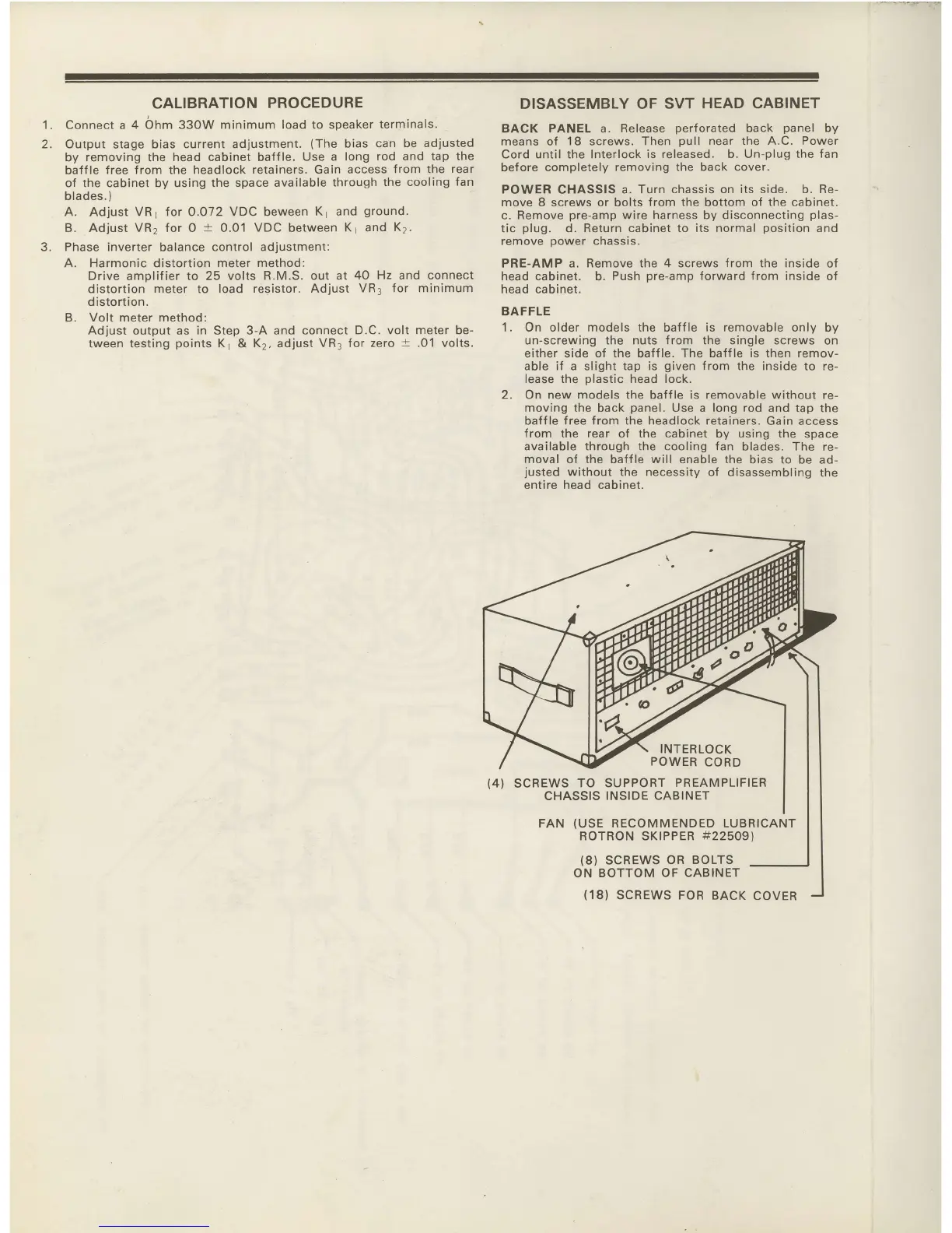
DISASSEMBLY OF
SVT HEAD CABINET
BACK PANEL a.
Release
perforated
back
panel
by
means of
18
screws.
Then
pull
near the A.C. Power
Cord until the Interlock
is released. b. Un-plug the
fan
before
completely
removing the back cover.
POWER
CHASSIS
a. Turn
chassis on its side. b. Re-
move 8 screws or bolts
from the
bottom
of the cabinet.
c.
Remove
pre-amp
wire harness by disconnecting
plas-
tic
plug.
d.
Return cabinet to its normal
position
and
remove
oower
chassis.
PRE-AMP a. Remove the 4 screws
{rom
the inside of
head
cabinet.
b.
Push
pre-amp
forward
Jrom
inside of
head cabinet.
BAFFLE
1. On older models the baf{le is removable only
by
un-screwing the nuts Jrom the single screws on
either side
of the
baffle.
The baffle is then remov-
able if a slight tap is
given
from
the inside
to
re-
lease the
olastic
head lock.
2. On new
models
the baff
le
is removable without re-
moving the back
panel.
Use a long rod and
tap the
baffle free from the headlock retainers.
Gain access
from
the rear o{ the cabinet by using the
space
available through the cooling fan
blades. The re-
moval of the baffle will enable the
bias to be ad-
justed
without the necessity of disassembling
the
entire head cabinet.
5.
SCREWS
TO SUPPORT
PREAMPLIFIER
CHASSIS
INSIDE CABINET
FAN
(USE
RECOMMENDED LUBRICANT
ROTRON SKIPPER
#225091
(8}
SCREWS
OR BOLTS
ON BOTTOM
OF CABINET
(18)
SCREWS
FOR BACK
COVER