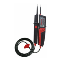
Controls and Connections
1. Handle test probe - (L1)
2. Instrument test probe + (L2)
3. LED row for voltage display
4. Measurement point illumination
(white LED)
5. LED for single-pole phase test (VP-710,
VP-720)
6. LED for rotary field (right-hand)
7. LED for continuity test Rx (VP-710,
VP-720)
8. LED for polarity and 12 V
9. LC display (VP-720)
10. Contact electrode (capacitive, integrat-
ed)
11. Pushbuttons for load application
12. Button for measurement point
illumination / switch on instrument
(VP-710, VP-720)
13. Test probe cover
14. Test probe cover (attached to test lead)
15. Grip area
17