14
2. For models with maximum output voltage below 60 Volts, Capacitance should not exceed 3000uF.
<NOTE:>
If load capacitance approaches these limits, it is recommended to not intentionally activate
the OVP circuit and discharge the capacitance through the SCR crowbar as part of
standard testing procedure.
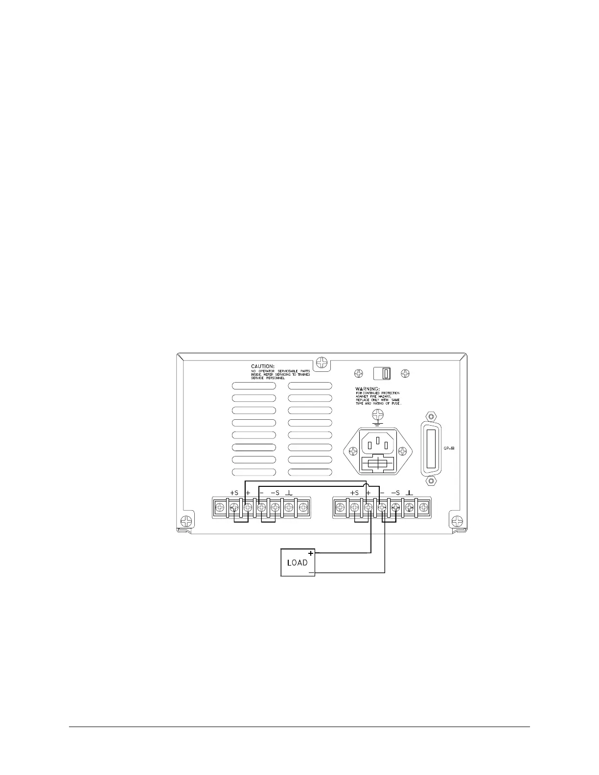
3.5 PARALLEL CONNECTION OPERATION
<NOTE:>
Power supplies equipped with SCR crowbars should not be used in series or parallel with
each other unless a master-slave interconnection is employed and their crowbars interlock.
Greater current capability can be achieved by connecting outputs in parallel. However, only power supplies
which have equivalent voltage and current output ratings may be connected in parallel. Otherwise, damage
to the unit may result.
A typical connection is shown in figure H through the back of PPS-2322 in local sensing. All leads are kept as
short as possible and are bundled together. Second, connect remote sense terminals to compensate for the voltage
drop in the interconnecting load leads. Lastly, the CV and CC operations have identical setups.
OUTPUT
channel 1
OUTPUT
channel 2
Figure H. Parallel Configuration
3.5.1 CV OPERATION
Although both outputs operate independently of each other in CV operation, one of the outputs must dominate
(control) over the other. Additionally, the dominant output must operate in CV mode, while the other output may
operate in CC mode.