18
3.7 External Analog Programming (PPS-1603/10710)
The voltage and current outputs of the PPS 1603/10710 can be programmed by an external analog voltage. The
outputs are linearly proportioned to an external input voltage from 0 to 10 volts. The external analog programming
mode is activated by setting these parameters via the front panel or GPIB bus, VSET to 0V, ISET to a proper value
for CV operation, or setting ISET to 0A and VSET to a proper value for CC operation.
To control the output voltage with the analog programming mode requires the following procedures, apply the
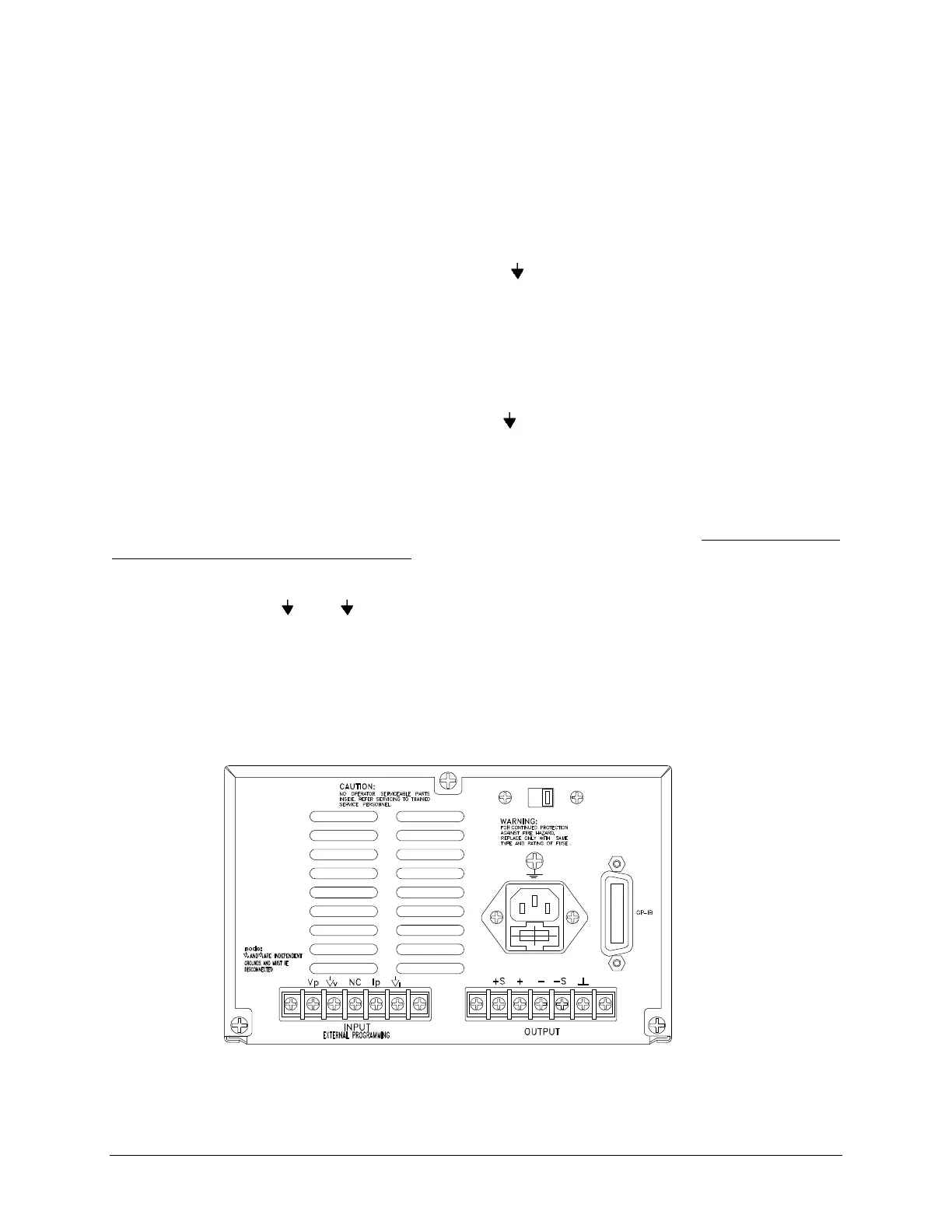
external 0 to 10V source (Vv-pgm) between Vp (positive) and v (common) terminals. These input terminals are
located at the rear of the power supply, see figure L.
The control output voltage is:
Vout = Vv-pgm * (Rated Maximum Output Voltage/ 10)
To control the output current with the analog programming mode requires the following procedure, apply the
external 0 to 10V source (VI-pgm) between Ip (positive) and I (common) terminals, see figure L.
The control output current is:
Iout = VI-pgm * (Rated Maximum output current / 10)
To control both voltage and current simultaneously in the external programming method requires that the user
apply two separately isolated 0 to 10V supplies.
<NOTES:>
Vp, Vn, v, and I are strapped with shorting straps.
Do not remove the straps unless activating the external analog programming mode.
The V and I terminals are at a negative sense potential, with this in mind do not connect
them to any other terminal on the rear panel. This precaution will prevent permanent
damage to the power supply!
Figure L. Rear Panel of PPS-1603/10710