5. Adjustments
and Checks
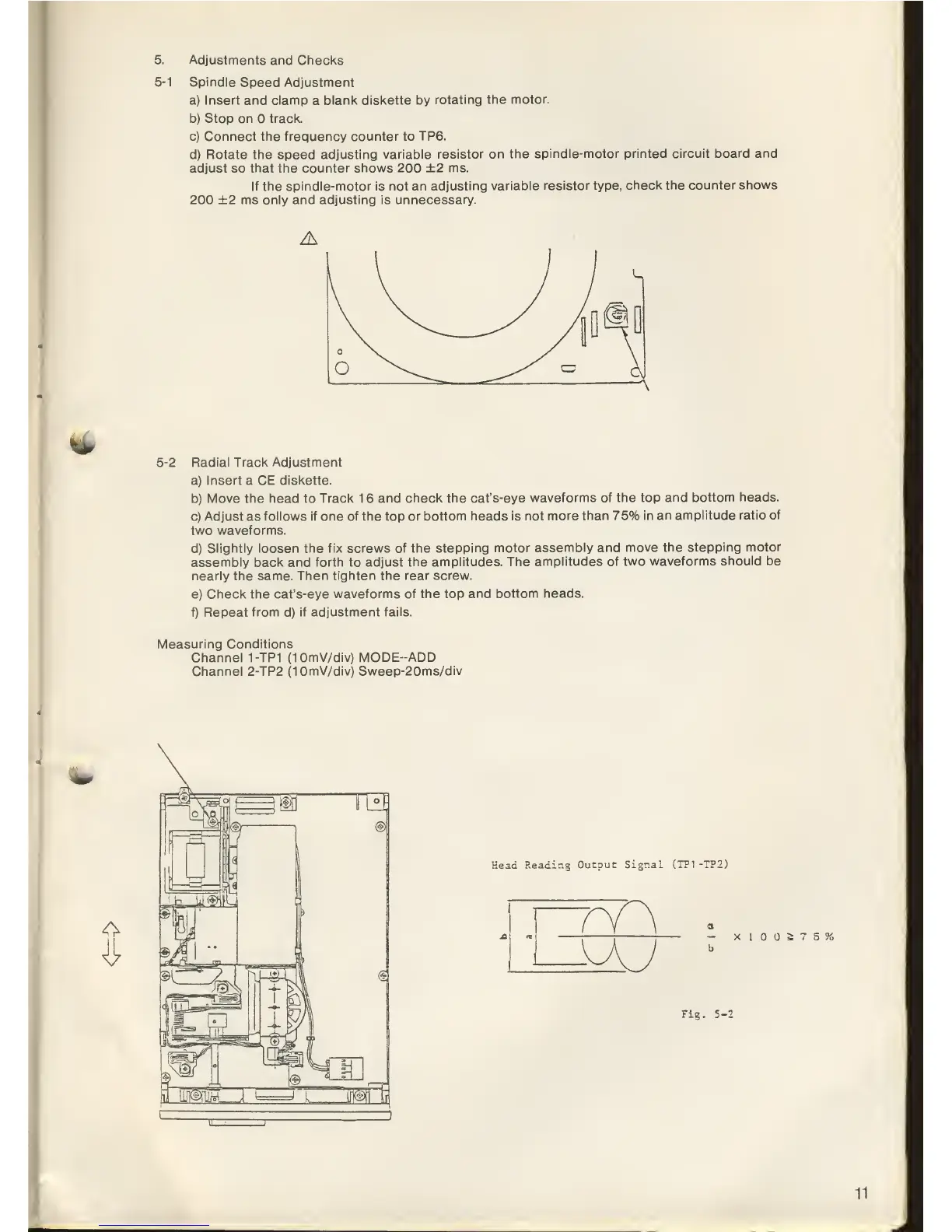
5-1
Spindle
Speed
Adjustment
a) Insert and clamp
a
blank diskette by
rotating
the motor.
b) Stop on track.
c) Connect the frequency counter to
TP6.
d) Rotate
the
speed
adjusting variable
resistor on the
spindle-motor
printed circuit board and
adjust
so
that the counter shows 200
+2
ms.
If the spindle-motor is not
an adjusting
variable resistor type,
check the counter
shows
200 ±2
ms only
and
adjusting is unnecessary.
fc^_
5-2
Radial Track Adjustment
a) Insert a CE
diskette.
b)
Move the head to Track 1 6
and check the cat's-eye
waveforms
of the
top
and bottom
heads.
c) Adjust as
follows if one of the top
or bottom heads is not
more than 75%
in an amplitude
ratio of
two waveforms.
d)
Slightly loosen the fix screws of
the stepping motor
assembly and
move the stepping
motor
assembly back and
forth
to adjust
the amplitudes.
The amplitudes
of two waveforms
should be
nearly the same.
Then tighten the rear screw.
e)
Check
the cat's-eye
waveforms of
the
top
and bottom heads.
f) Repeat from
d)
if
adjustment fails.
Measuring Conditions
Channel
1-TP1
(10mV/div) MODE-ADD
Channel 2-TP2 (10mV/div)
Sweep-20ms/div
Head
Reading
Outouc Signal
(TP1 -TP2)
—
X
I
2;
7
5 %
b
Fig.
5-
11