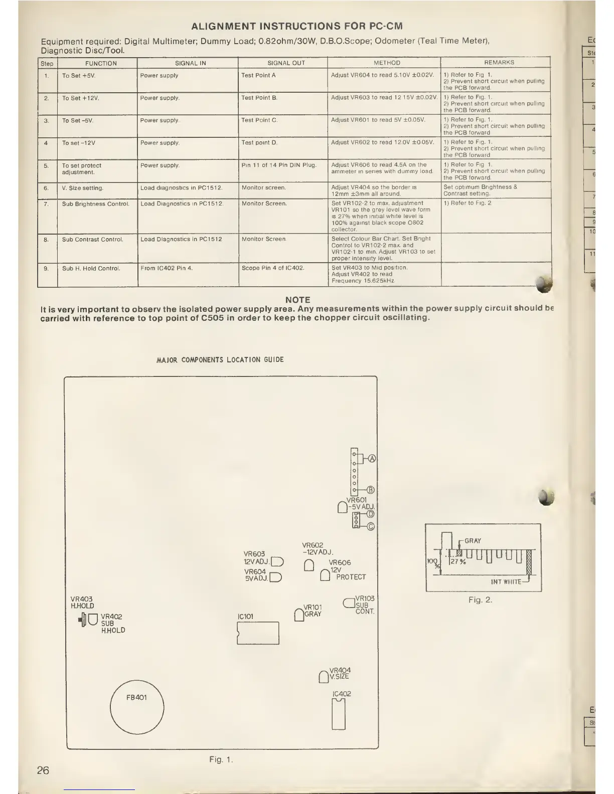
ALIGNMENT INSTRUCTIONS
FOR PC-CM
Equipment
required: Digital
Multimeter; Dummy
Load;
0.82ohm/30W, D.B.O.Scope;
Odometer
(Teal Time
Meter),
Diagnostic
Disc/Tool.
Step
FUNCTION
SIGNAL IN
SIGNAL OUT
METHOD
REMARKS
1. To Set
+5V.
Power supply. Test
Point A Adjust VR604 to
read 5.10V ±0
02V.
1)
Refer to
Fig. 1.
2)
Prevent
short circuit when
pulling
the
PCB
forward.
2. To Set
+ 12V.
Power supply. Test
Point B.
Adjust VR603 to
read
12
15V +0.02V.
1)
Refer to
Fig. 1.
2)
Prevent short circuit when
pulling
the PCB
forward.
3. To Set
-5V.
Power supply. Test
Point
C.
Adjust
VR601 to read 5V
±0.05V.
1)
Refer to Fig.
1.
2)
Prevent
short circuit when pulling
the PCB
forward.
4. To set
-1
2V.
Power supply.
Test point D.
Adjust
VR602
to
read 12.0V ±0.05V.
1)
Refer to
Fig.
1.
2)
Prevent short
circuit when pulling
the PCB
forward.
5. To set
protect
adjustment.
Power supply.
Pin 11 of 14 Pin DIN Plug.
Adjust VR606 to read 4.5A on
the
ammeter in series
with dummy load.
1)
Refer to
Fig. 1.
2)
Prevent short circuit when
pulling
the PCB forward.
6. V. Size
setting. Load
diagnostics in PC1512.
Monitor screen. Adjust
VR404
so
the
border
is
1
2mm ±3mm all around.
Set
optimum
Brightness
&
Contrast
setting.
7.
Sub Brightness
Control. Load
Diagnostics in PC1512. Monitor
Screen. Set VR
102-2
to
max. adjustment
VR101 so
the grey level wave
form
is 27%
when initial white level is
100%
against black scope Q302
collector
1)
Refer
to
Fig. 2.
8. Sub
Contrast
Control. Load Diagnostics in PC1512.
Monitor
Screen. Select Colour
Bar Chart. Set
Bright
Control to VR102-2
max. and
VR1
02-1
to
min. Adjust VR1 03 to
set
proper intensity level.
9.
Sub H. Hold
Control. From IC402
Pin 4. Scope Pin 4 of
IC402. Set VR403 to
Mid position.
Adjust
VR402 to read
Frequency 15.625kHz.
m
NOTE
It is
very
important to
observ the isolated power
supply area. Any
measurements
within the power
supply
circuit should be
carried
with reference
to top point
of
C505
in order to keep
the chopper
circuit
oscillating.
MAJOR
COMPONENTS LOCATION
GUIDE
VR403
H.HOLD
00
VR402
SUB
H.H0LD
:^s>
oj—
®
„VR601
(1-5VADJ.
VR603
12V
ADJ.
Q)
VR604
.
—
.
5VADJ.LJ
IC101
VR602
-12V
ADJ.
Q
VR606
12V
Q
VR101
IGRAY
PROTECT
,—
iVR103
LJsub
CONT.
Qv.size
IC402
r-GRAY
-f:phnr
f^uyuuui
iNTWurrt
J
Fig. 2.
Fig.
1.
26