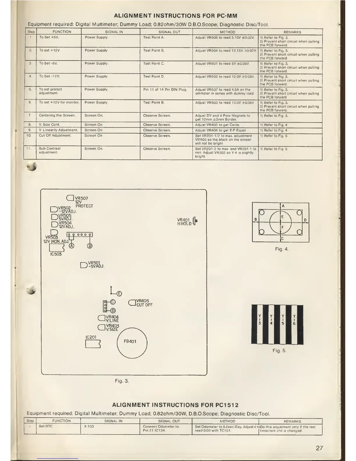
ALIGNMENT
INSTRUCTIONS
FOR PC-MM
Equipment required:
Digital Multimeter;
Dummy Load; 0.82ohm/30W
D.B.O.Scope; Diagnostic Disc/Tool.
Step FUNCTION
SIGNAL
IN
SIGNAL OUT METHOD
REMARKS
1. To Set +5V. Power Supply.
Test Point A. Adjust VR505 to read 5.10V
±0.02V.
1)
Refer to Fig. 3.
2)
Prevent
short circuit when
pulling
the PCB forward.
2 To set+12V
Power Supply.
Test Point B. Adjust VR504
to
read
1
2.1
5V ±0.02V.
1)
Refer
to
Fig. 3.
2)
Prevent short circuit when pulling
the
PCB forward.
3. To Set -5V. Power
Supply.
Test Point
C.
Adjust
VR501 to
read
5V ±0.05V.
1)
Refer to Fig. 3.
2)
Prevent short circuit
when pulling
the
PCB
forward.
4.
To Set -12V. Power
Supply.
Test Point D. Adjust VR502
to
read
1 2.0V ±0.05V.
1)
Refer to Fig. 3.
2)
Prevent short circuit when pulling
the
PCB
forward.
5.
To set protect
adjustment.
Power
Supply.
Pin 11 of 14 Pin DIN Plug. Adjust
VR507 to
read
4.5A
on the
ammeter in series with dummy load.
1)
Refer to Fig. 3.
2)
Prevent short circuit when pulling
the
PCB
forward.
6. To set +1 2V tor monitor.
Power Supply.
Test Point B. Adjust
VR503 to
read
12.0V ±0.05V.
1)
Refer
to
Fig. 3.
2)
Prevent short circuit when pulling
the PCB forward.
7. Centering the Screen.
Screen On.
Observe Screen.
Adjust DY
and
4
Pole
Magnets to
get
12mm
±3mm Border.
1|
Refer
to Fig. 3.
8. V. Size
Cont. Screen On.
Observe Screen.
Adjust VR403 to get Circle.
1)
Refer
to
Fig.
4.
9. V. Linearity Adjustment. Screen
On.
Observe Screen. Adjust VR404
to get E-F
Equal.
1)
Refer to Fig. 4.
10.
Cut
Off Adjustment.
Screen On.
Observe Screen.
Set VR20M/2 to max. adjustment
VR405 so the. black on the screen
will not be bright.
1)
Refer
to
Fig.
5.
11. Sub Contrast
adjustment.
Screen
On
Observe Screen.
Set
VR201-2
to
max.
and VR20M to
min. Adjust VR203
so
Y-4 is slightly
bright.
1)
Refer to Fig. 5.
->
P2)VR502
QVR507
^12V
PROTECT
12V
ADJ.
DM.
r>iVR504
'12V
ADJ.
VR401
H.HOLD
D
VR503
12VM0N.ADJ
IC503
\ym
DJ.
u
QVR405
CUT
OFF
|0|
<D)
aVR404
V.LINE
aVR403
V.SIZE
IC201
I
FB401
]
A
B
v
?N
D
b^
y
O
c
Fig.
4.
Fig.
5.
Fig.
3.
ALIGNMENT
INSTRUCTIONS
FOR PC1512
Equipment
required:
Digital Multimeter;
Dummy
Load; 0.82ohm/30W, D.B.O.Scope;
Diagnostic Disc/Tool.
Step
FUNCTION
SIGNAL
IN SIGNAL
OUT
METHOD
REMARKS
Set RTC
X-103
Connect
Odometer to
Pin
21 IC134.
Set Odometer to
0.2sec/Day.
Adjust
it toDo this adjustment only if the real
read
0.00 with TC101. I timeclock chil
is changed.
27