Continuum CPU Reference
7
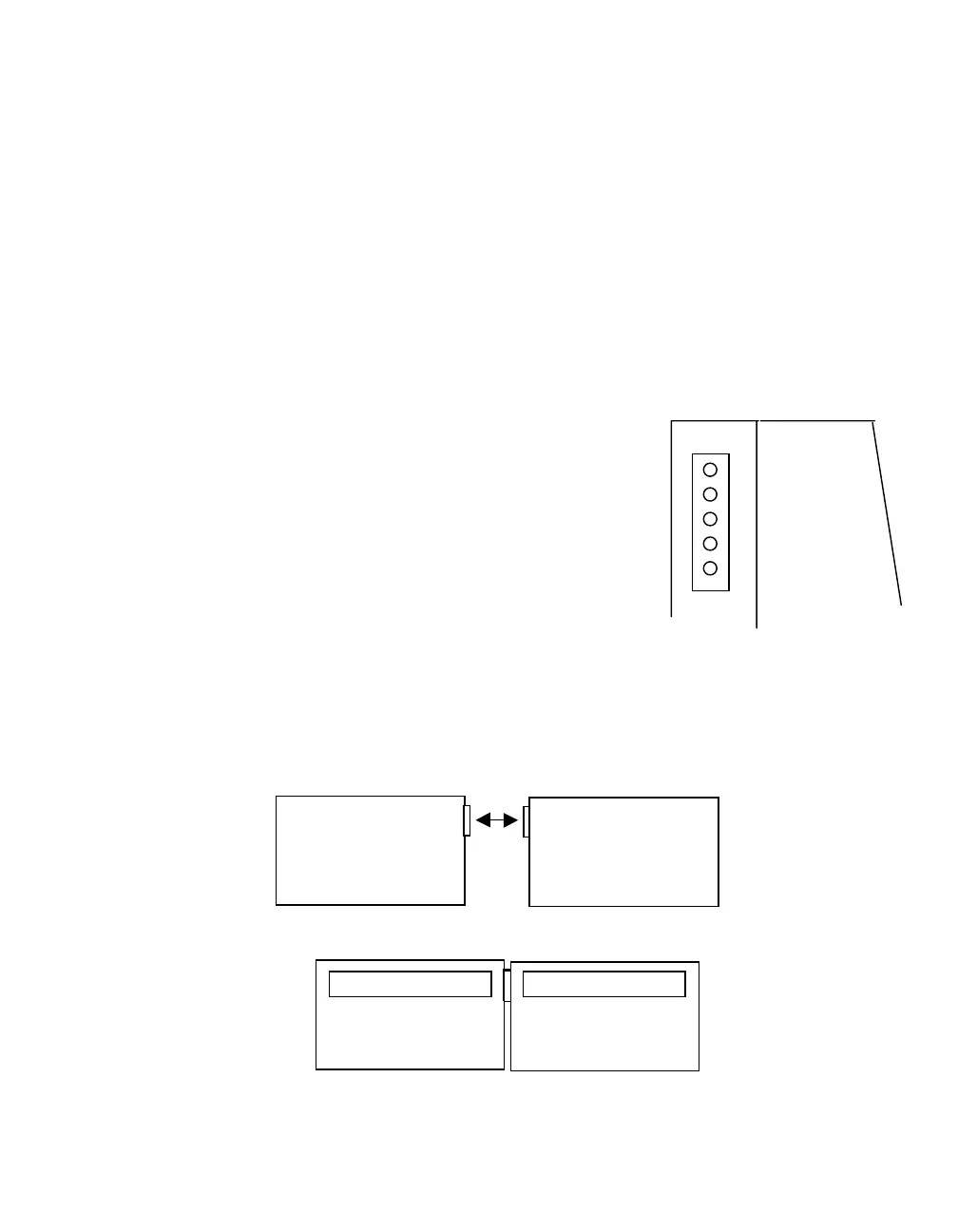
DC Power Connection
The CPU module is powered by an external 24 VDC source. This source is supplied
by one of the three
Continuum
Power Supply Modules. The input power connector is
located on the left side of the CPU module case and consists of five pins.
The power input connector is a five-pin male assembly that is designed to easily
insert directly into the right side (output) connector of any Power Supply module. The
signals within that connector are as follows:
PIN Function
5 +24 VDC
4 24 VDC Return
3 Ground
2 Low Battery *
1 AC Power *
* Only supplied from PS 120/240 AC 50-U Power Supply
It is assumed that the CPU is directly connected to a power supply module as shown
below:
5
Power Suppl
CPU