Continuum CPU Reference
9
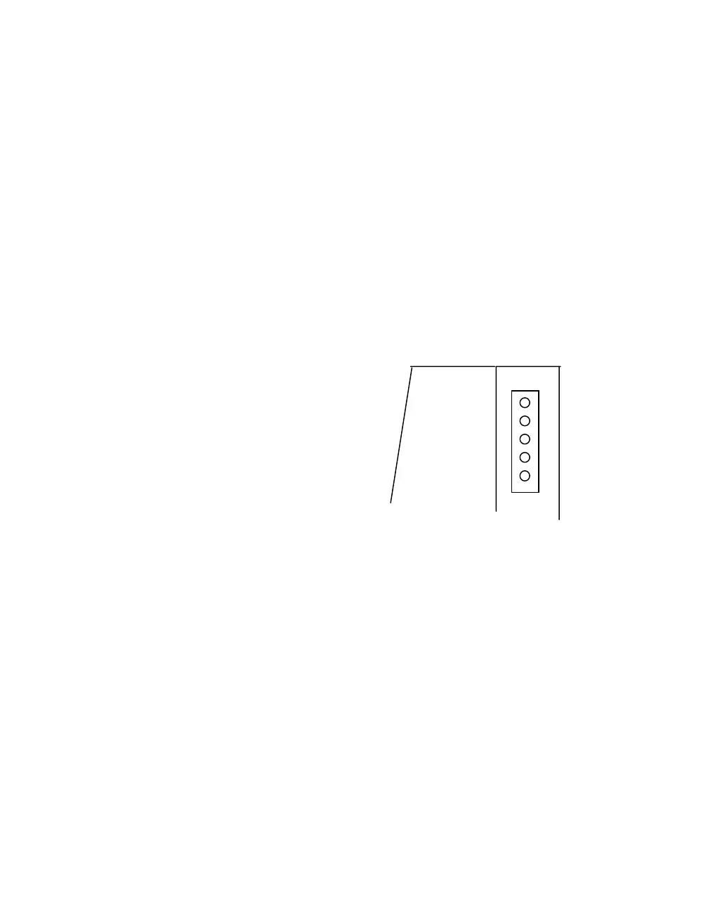
Output Power-I/O Connections
The
Continuum
NetController module includes a connector on the upper right side of
the case for further distribution of the 24 VDC input power and special I/O
communications signals. Continuum I/O modules use these signals for power and
communications as well.
The power-I/O connector is a five-pin male assembly that is designed to easily insert
directly into the left side (input) connector of any I/O module. The signals within that
connector are as follows:
PIN Function
5 +24 VDC
4 24 VDC Return
3 Ground
2 Comm B
1 Comm A
The power supply generates a +24 VDC source for all modules in the system. This
power source is received through the input power connector on the left side of the
CPU module and sent through to pins 4 and 5 of this connector. Pin 3 (Ground) is
intended as a signal ground connection.
Communications between the CPU and I/O modules is through a two signal serial
interface that can be internally configured as either RS 485 or Echelon LON FTT-10.
Pins 1 and 2 (Comm B and Comm A) provide the electrical connection for this
interface.
5