12
Andover Controls
Termination Guidelines
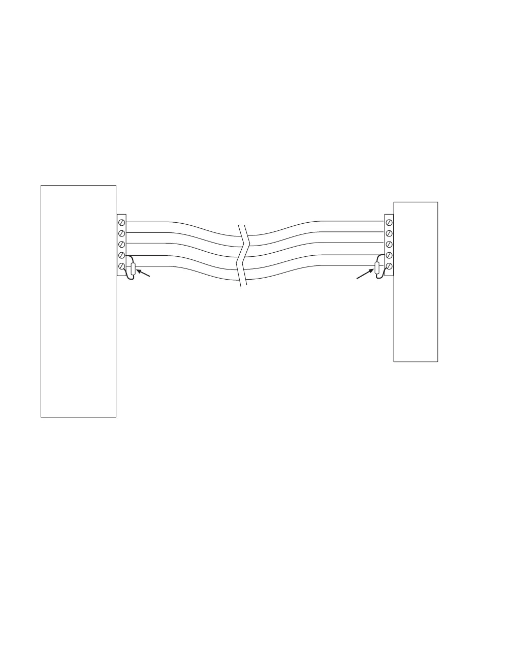
The following are typical installations that indicate the placement of the terminator:
Simple CPU and 1 remote I/O Module:
The I/O Bus that needs to be terminated is the one formed by the cable attaching the
remote module to the CPU. In this case, a terminator resistor is connected across the
communications lines (pins 1 & 2) directly at the NetController and again at the remote
I/O module.
CPU
5
4
3
2
1
5
4
3
2
1
120 Ω
Resistor
120 Ω
Resistor
Remote
I/O
Module