Continuum CPU Reference
15
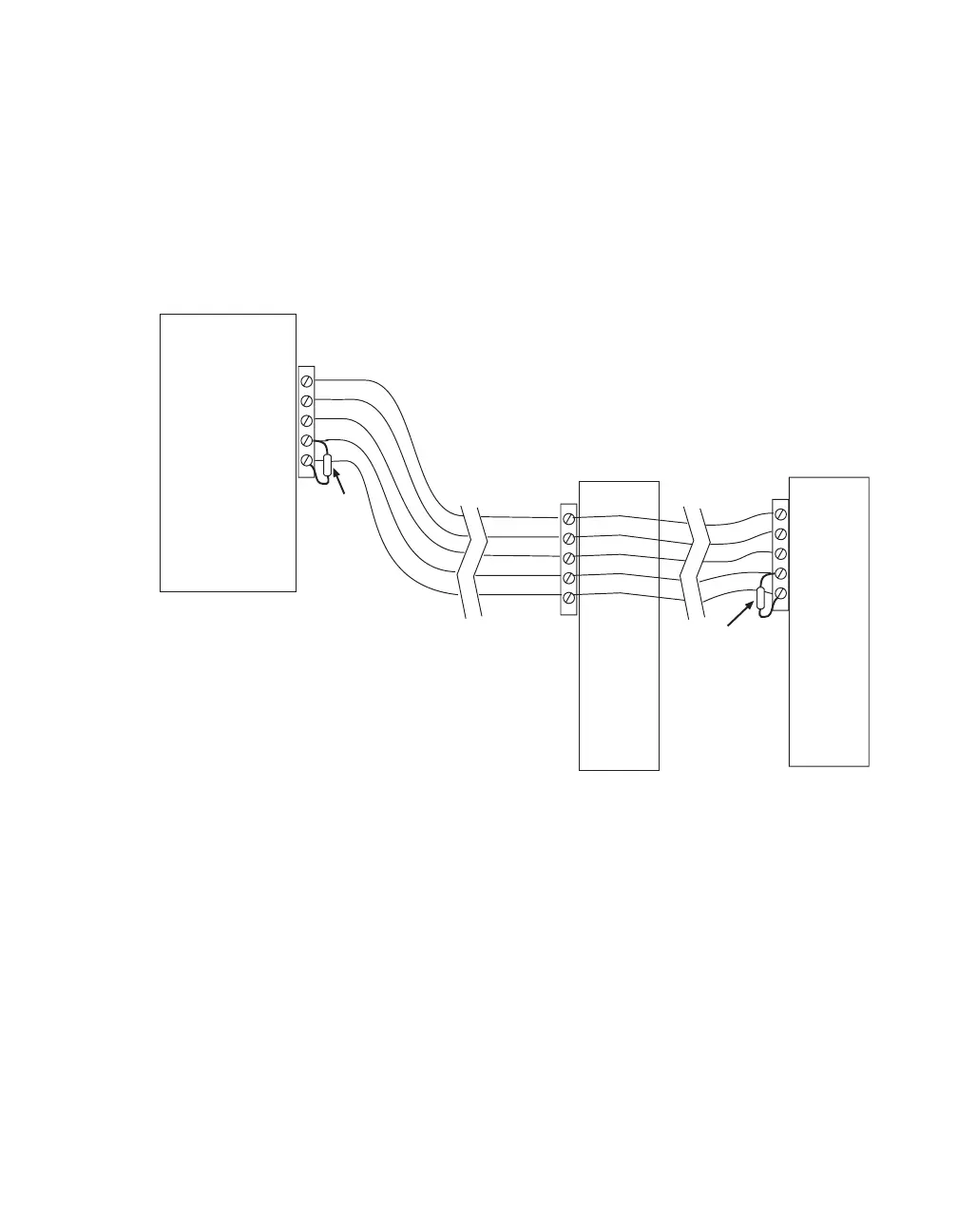
CPU with two remote modules separated by distance:
The I/O Bus that needs to be terminated is the one formed by both cables on either
end of the first remote I/O module. In this case, the bus begins at the NetController,
flows by the first remote module and ends at the second. The terminator resistor is
connected directly across the communications lines (pins 1 & 2) at the NetController
and again at the last remote I/O module. If the last module is actually a stack of
directly connected I/O modules, the terminator is placed at the first module of the
stack as indicated in the scenario described on the previous page.
CPU
5
4
3
2
1
5
4
3
2
1
120 Ω
Resistor
120 Ω
Resistor
Remote
I/O
Module
Remote
I/O
Module
5
4
3
2
1