Continuum CPU Reference
19
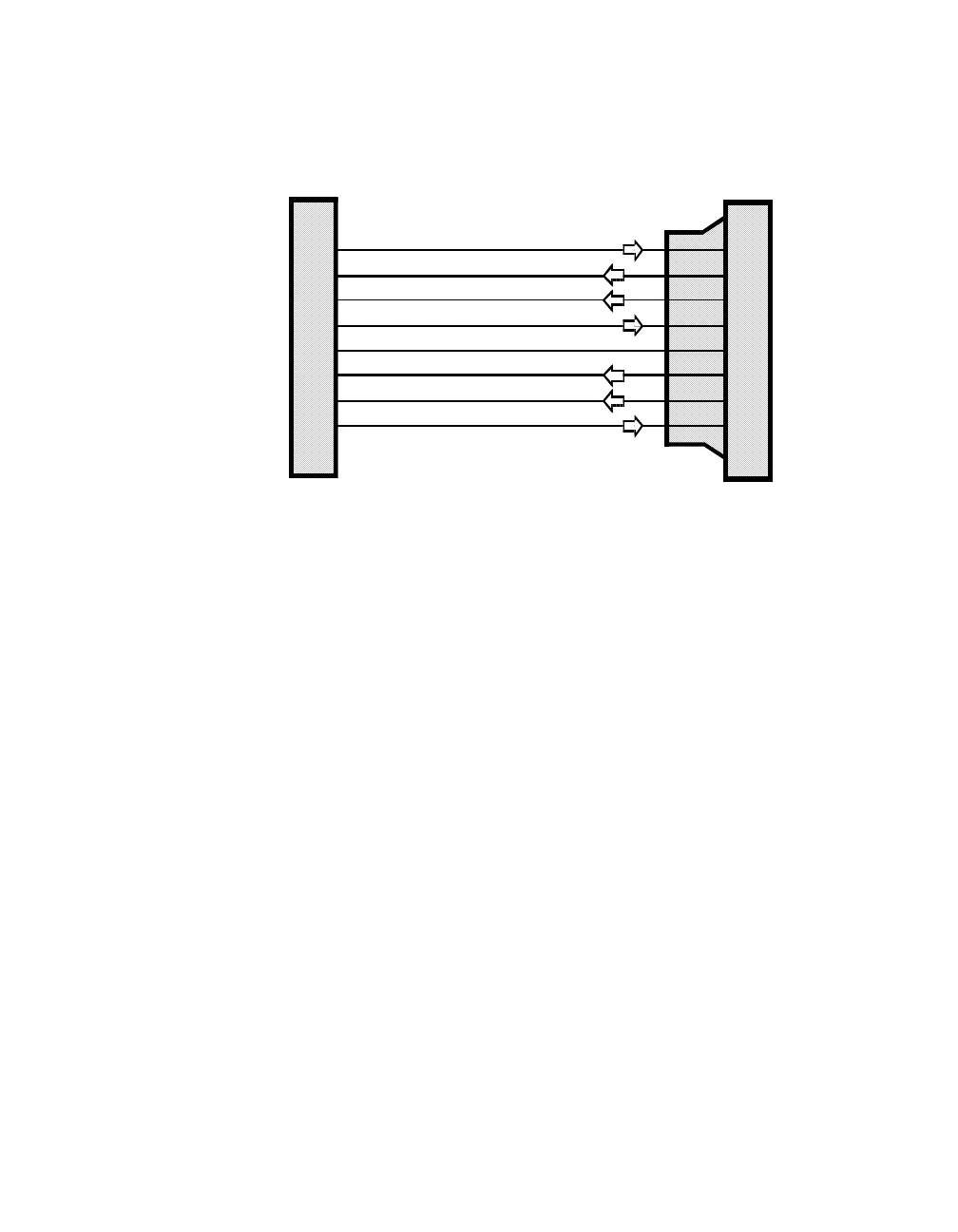
Connection to a standard RS-232 device using a cable terminated with an RJ-45 and
25-pin D-type connector are shown below:
Use a cable of this type to connect to printers and other devices. Depending on the
device, it may be necessary to reverse the RD and TD connections. This can easily
be accomplished using an adapter called a “null modem”.
RS-232 COMM Port Configuration
After physical connection, the COMM Port must be configured as an RS-232 device
properly through the
Continuum
workstation. Configuration requires selecting the
type of device to be connected (i.e., Printer, Command, etc.) and setting various
communications-related parameters. Refer to the on-line help system of the
Continuum
workstation for detailed information regarding configuration issues.
1
2
3
4
5
6
7
8
2
6
3
7
4
8
5
20
TD
(Transmit Data)
DSR
(Data Set Ready)
RD
(Receive Data)
Signal RTN
(Signal Return)
RTS
(Ready to Send)
DCD
(Data Carrier Detected)
CTS
(Clear to Send)
DTR
(Data Terminal Ready)
RJ-45 Connector
at CommPort
Standard DB-25 Connecto
(25-Pin Male)
Straight-Through Cable