Do you have a question about the andrews L40/36 and is the answer not in the manual?
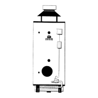
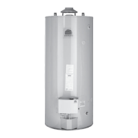
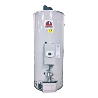
Provides a general description of the heater and its intended use.
Lists relevant British standards and codes of practice for installation.
Details legal requirements and regulations for safe installation and operation.
Discusses the heater's resistance to Legionella bacteria and safety measures.
Presents technical specifications for the Standard Range of water heaters.
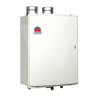
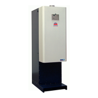
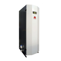
Presents technical specifications for the Hi-Flo Range of water heaters.
Outlines legal requirements, regulations, and standards for proper installation.
Provides step-by-step instructions for assembling the draught diverter.
Offers guidance on selecting installation sites and required clearance specifications.
Details requirements and procedures for connecting the LPG gas supply.
Provides instructions for connecting LPG cylinders and manifold systems.
Details electrical connection requirements for auto ignition models.
Outlines recommendations and requirements for proper flue installation.
Provides guidelines for ensuring adequate air supply and ventilation.
Information on water quality, anode maintenance, and scale prevention measures.
Details the Hydrojet system and general water connection procedures.
Provides specifics for connecting Standard Range models in vented water systems.
Provides specifics for connecting Standard Range models in unvented water systems.
Provides specifics for connecting Hi-Flo Range models in vented water systems.
Provides specifics for connecting Hi-Flo Range models in unvented water systems.
Commissioning procedures for Standard Range Permanent Pilot models.
Details the procedure for safely shutting down the burner.
Explains the method for verifying main burner pressure.
Step-by-step guide for lighting the burner on Hi-Flo Range models.
Provides guidance on how to inspect the pilot flame's shape and size.
Covers commissioning steps for Standard Range Auto Ignition models.
Details the procedure to check for flue product spillage at the draught diverter.
Provides guidance for end-user operation, maintenance, and safety.
Presents essential safety instructions and warnings for appliance users.
Describes the operating sequence for Standard Range auto ignition models.
Describes the operating sequence for Hi-Flo Range models.
Explains the function of the overheat safety cut-off (ECO) device.
Describes temperature stratification (stacking) and methods to prevent it.
Provides general advice and recommendations for servicing the water heater.
Outlines preliminary steps to be taken before commencing servicing.
Instructions for cleaning and servicing the burner assembly on Standard Range models.
Instructions for cleaning and servicing the burner assembly on Hi-Flo Range models.
Details servicing procedures for the gas control valve on Standard Range models.
Details servicing procedures for the gas control valve on Hi-Flo Range models.
Procedures for checking and cleaning flue ways on Standard Range models.
Procedures for checking and cleaning flue ways on Hi-Flo Range models.
Details the method for cleaning the storage vessel.
Provides guidelines and procedures for descaling the water heater.
Covers maintenance and replacement of magnesium anodes.
Provides instructions for checking and servicing the safety valve on Hi-Flo Range models.
Details the steps for restarting the heater after servicing.
Steps for replacing the gas control valve on Hi-Flo models.
Instructions for replacing thermostat and overheat components.
Instructions for replacing the thermopile, pilot burner, and restrictor.
Instructions for replacing the burner assembly.
Troubleshooting ignition faults for Standard Range auto ignition units.
Fault finding and troubleshooting for permanent pilot models.
Illustrated parts and diagrams for Standard Models L24/31, L32/35, L40/36, L63/71.
Illustrated parts and diagrams for Standard Model L84/74.
Illustrated parts and diagrams for Hi-Flo Models.
Provides the parts list for the 24 Volt Auto System Kit.
Presents an exploded view of parts for Hi-Flo Model L32/143.
Presents an exploded view of parts for Hi-Flo Models L65/169, L81/251.
Lists parts for the Unvented Systems Kit (Standard Range).
Lists parts for the Unvented Systems Kit (Hi-Flo Range).
| Model | L40/36 |
|---|---|
| Heating Capacity | 36 kW |
| Voltage | 400 V |
| Phase | 3 |
| Frequency | 50 Hz |
| Protection Rating | IPX4 |