31
CH0305-134
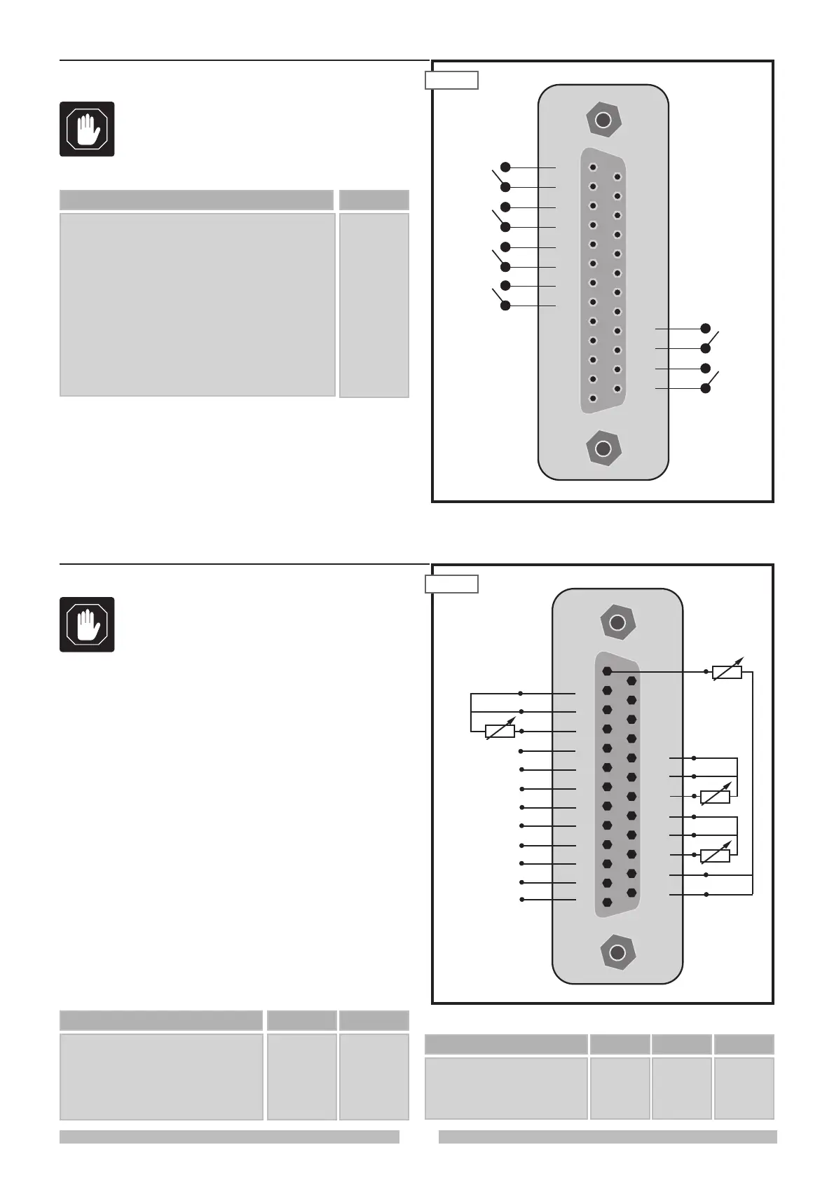
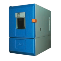
6.11
ANALOGIC IN/OUT Connector (5.3)
IA 1
IA 2
IA 3
IA 4
IA 5
IA 6
1
3
4
6
7
9
2
2
5
5
8
8
ANALOGIC INPUT PIN (+) PIN (-)
PT 1
PT 2
PT 3
PT 4
10
13
16
19
PT100 PROBE INPUT PIN ONLY
11
14
17
20
PIN B
12
15
18
21
PIN A
If the user has put his own sensors inside the test chamber
which produce analogic signals (0-10 V or 0-20 mA), these
may be acquired by the built-in computer and visualized
and/or memorized.
The type of configuration for each channel is set at the
factory on special jumpers on the µPLC board.
The description of the connector pins follows below:
This connector is used to connect to the control system:
• probes PT 100 (RTD) to be placed inside the
chamber, to be connected to terminals PT1, PT2,
PT3, PT4.
• Proportional signals to be connected to inputs IA1,
IA2, IA3, IA4, IA5, IA6.
CH0305-132
6.10
DIGITAL IN/OUT connector (5.2)
A- Clean contact NO (AUX 1 output)
B- Clean contact NO (AUX 2 output)
C- Clean contact NO (AUX 3 output)
D- Clean contact NO (AUX 4 output)
E- Clean contact NO (user’s equipment)
F- Clean contact NO for remote control alarm
1 - 2
3 - 4
5 - 6
7 - 8
22 - 23
24 - 25
OUTPUT DESCRIPTION PIN
A
B
C
D
E
F
1
2
3
4
5
6
7
8
9
10
11
12
13
14
15
16
17
18
19
20
21
22
23
24
25
1
2
3
4
5
6
7
8
9
10
11
12
13
14
15
16
17
18
19
20
21
22
23
24
25
These configurations on the connectors
will be activated on request.
These configurations on the connectors
will be activated on request.
(IA2) 4-20mA/0-10V
(IA1) 4-20mA/0-10V
(IA3) 4-20mA/0-10V
(IA4) 4-20mA/0-10V
(IA5) 4-20mA/0-10V
(IA6) 4-20mA/0-10V
+
-
-
-
+
+
+
+
+
RTD
RTD
RTD
RTD
PT1
PT2
PT3 PT4