5.10
FOR
ELECTROMAGNETIC INTERFERENCE
5.10
1
On Radar Installation
Anritsu radar provides shields in the units and
the inter
-
unit connection cable.
When the radar, however, is closely installed to radio
equipment such as Loran receiver, Omega receiver,
Transceiver etc.,
or
the radar and/or radio equipment are
not sufficiently grounded to the hull or ship's earth,
the radar
may
happen to cause
EM1
trouble.
Followings are general procedures for reducing
EM1 due
to radars. When installing radars, refer to them, and
also check the radio equipment
EM1
trouble with
operating the radar and the radio equipment.
(1)
Installation Place
of
Radar
The display unit, scanner unit and inter
-
unit
connection cable should be located apart from the main
unit, feeder, antenna coupler and antenna of radio
equipment as far as possible.
Especially, proper installation
of
the feeder, antenna
coupler and antenna of radio equipment is very important
to improve
EM1 trouble.
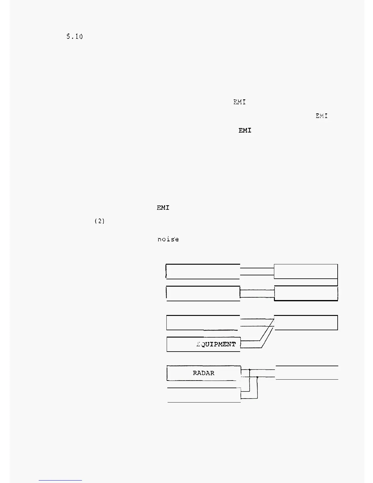
(2)
Laylng Power Supply Cables
Following connections A and
B
are recommended to reduce
conduction
noise generated from radar. Connection
C
should not be used.
RADAR
I
I
.
Connection
A
SHIP'S SUPPLY
1
RADIO EQUIPMENT
I]
SHIP'S SUPPLY
I
.
Connection B
I
I
I
I
RADAR SHIP'S SUPPLY
RADIO
-2UIPMENT
Connection
C
SHIP'S SUPPLY
(Bad)
RADIO EQUIPMENT
-t!.J
5
-
12