Do you have a question about the Antminer S9 and is the answer not in the manual?
Lists essential tools for operation board maintenance, including soldering irons and test equipment.
Outlines necessary knowledge, experience, and proficiency for maintenance personnel.
Explains the basic structure, voltage domains, and chip composition of the S9 board.
Details the flow direction of CLK, TX, RX, B/BO, and RST signals across chips.
Identifies specific test points located between chips on the S9 computing board.
Explains the 21 voltage domains and how power is supplied to associated components.
Presents the detailed circuit diagram for the BM1387 chip.
Lists and describes the function of each pin on the BM1387 chip.
Outlines voltage checks when the IO line is not connected.
Details voltage checks when the IO line is connected and the test key is pressed.
Explains expected voltages for CORE, LDOs, and PLL, and their relation to faults.
Details voltage measurements at peripheral test points and their significance.
Defines the purpose and function of each pin on the IO port.
Explains how to identify and measure signal voltages on the board.
Explains the function of the 14V boost circuit and provides its schematic diagram.
Shows the physical layout of the 14V boost circuit on the PCB.
Details the DC-PIC's role in storing information and controlling voltage, with its schematic.
Explains the DC-DC circuit and provides its schematic diagram.
Lists and explains the primary functions of the LM27402SQ chip's pins.
Provides steps to diagnose and resolve DC-DC voltage output issues.
Details the 25M clock circuit, crystal oscillator, and its operational principle.
Covers the 1.8V LDO circuit and the temperature sensing mechanism.
Addresses the issue where the mining interface shows no configuration information.
Provides methods for diagnosing and resolving common mining machine errors.
Describes the specific error state of no real-time hash rate and a flashing red light.
Details potential issues related to the 25M clock circuit.
Covers problems like dropped lines, less board, and dropped chips.
Addresses phenomena like less mining machine, chip hit X, and reduced performance.
Discusses issues with detecting boards or chips and connection problems.
Explains the state of no real-time hash rate with alarms and red light flashes.
Describes chip status as 'XX' and reduced GH/S(AVG) performance.
Details the condition of no real-time hash rate with red flashing lights.
Covers scenarios where only one fan is detected, leading to protection mechanisms.
Addresses low average hash rate accompanied by chip errors.
Details instances where the real-time hash rate is abnormally high.
Describes the state of no real-time hash rate, red light flashes, and alarms.
Explains the cause and checks for the red light alarm indicating no real-time hash rate.
Discusses common phenomena related to control panel problems and firmware.
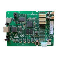
Describes the C5 control system and its components.
Provides details about the XILINX control panel.
Shows the visual appearance of the C5 and XILINX control panels.
Outlines the sequential steps for performing routine inspections and tests.
Classifies common faults such as heat sink issues, impedance, and voltage imbalances.
Explains how to detect missing chips using test box results and signal tracing.
Details faults like broken chains and the system failing to operate.
Explains reasons for low calculation capacity and how to diagnose them.
Emphasizes the importance of technician knowledge regarding test points, voltages, and chip welding.
Provides crucial precautions for chip replacement, including cleaning and heating.
| Voltage | 11.60 ~13.00V |
|---|---|
| Chip Type | BM1387 |
| Network Connection | Ethernet |
| Weight | 4.2kg |
| Number of Chips | 189 |
| Cooling | 2 x 12038 fans |
| Operating Temperature | 0 - 40 °C |
| Dimensions | 350mm x 135mm x 158mm |