S9 Operator Board Maintenance Instructions
13T Operation Board
:
8.4 V-8.9 v
12.5T Operation Board: 8.5 V 9.1 V
12T the following operational board:8.6-9.2 V
If this range is exceeded
,
please check DC-DC Circuit.
7
、
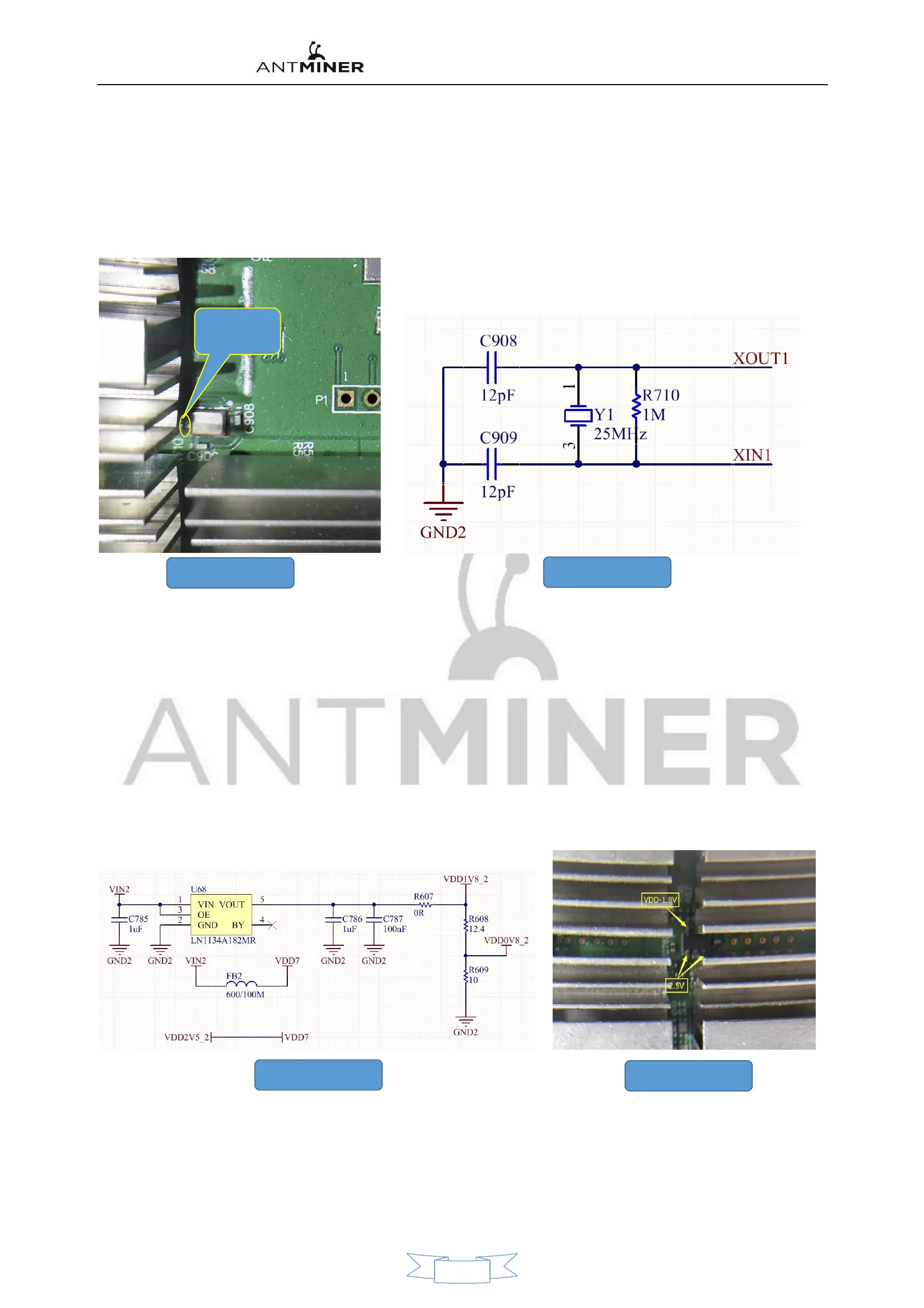
25M Clock and 25MHZ Passive crystal oscillator and 12pF Composition
:
As shown in figure 17 and Figure 18
R70 Both
ends power
1v Around
17
、
25M LCK Circuit
18
、
25M LCK Principle
Normal time
,
R70 Each end voltage is 1v Around.
8
、
1.8V-LDO by 1.8 VLDO SPX5205M5_L_1_8 Composition
Figure 19 and Figure 20 is shown
:
SPX5205M5 pin 1, 3 as input
,
pin 5 for 1.8V Output
;
It is important to note that
:
S9 of the Operation board LDO There are two modes of power supply operation. One is that each voltage domain of an
operational board is an external LDO ,SPX5205M5
,
Responsible for each voltage domain's
3 A chip. LDO
;
The other is only the last 6 Voltage domain Setting External LDO
,
The other voltages are built-in by the chip. LDO Provide yourself
;
BM1387
Chips are
Ready-built LDO Power supply Circuit
,由
BM1387
的
14
(
LDO-25I
)
pin input
,
10
脚(
LDO-18th
)
Output
,
And each chip has a separate
LDO
,
Non-interference.
At last 6 Voltage domain. LDO-25I The power supply is from 14V Boost circuit
;
Other voltage-domain LDO-25I is by the rear 6
Voltage domain. CORE Voltage superposition gain
(
6 *. 04V = 2.4 Around
)。
PLL-08 Voltage by LOD-1.8 It is obtained by two resistance voltage divider.
19
、
25M LCK Circuit
20
、
25M LCK Circuit
8, Temperature sensing circuit
:
There are two warm senses
,
one is TEMP
(
PCB
),
This is
by the sensor IC Constitute
;
The other is
TEMP
(
CHIP
),
This is a temperature sensor set built into the chip.
(
BM1387 pin 15
,
pin 16
),
Two temperature sensing parameters are collected and finally passed BM1387
第
17
、
18
脚,由
Re Back to the Control Panel FPGA
。
Principle as shown 21 is shown
11


 To Next Page