Fig. 3
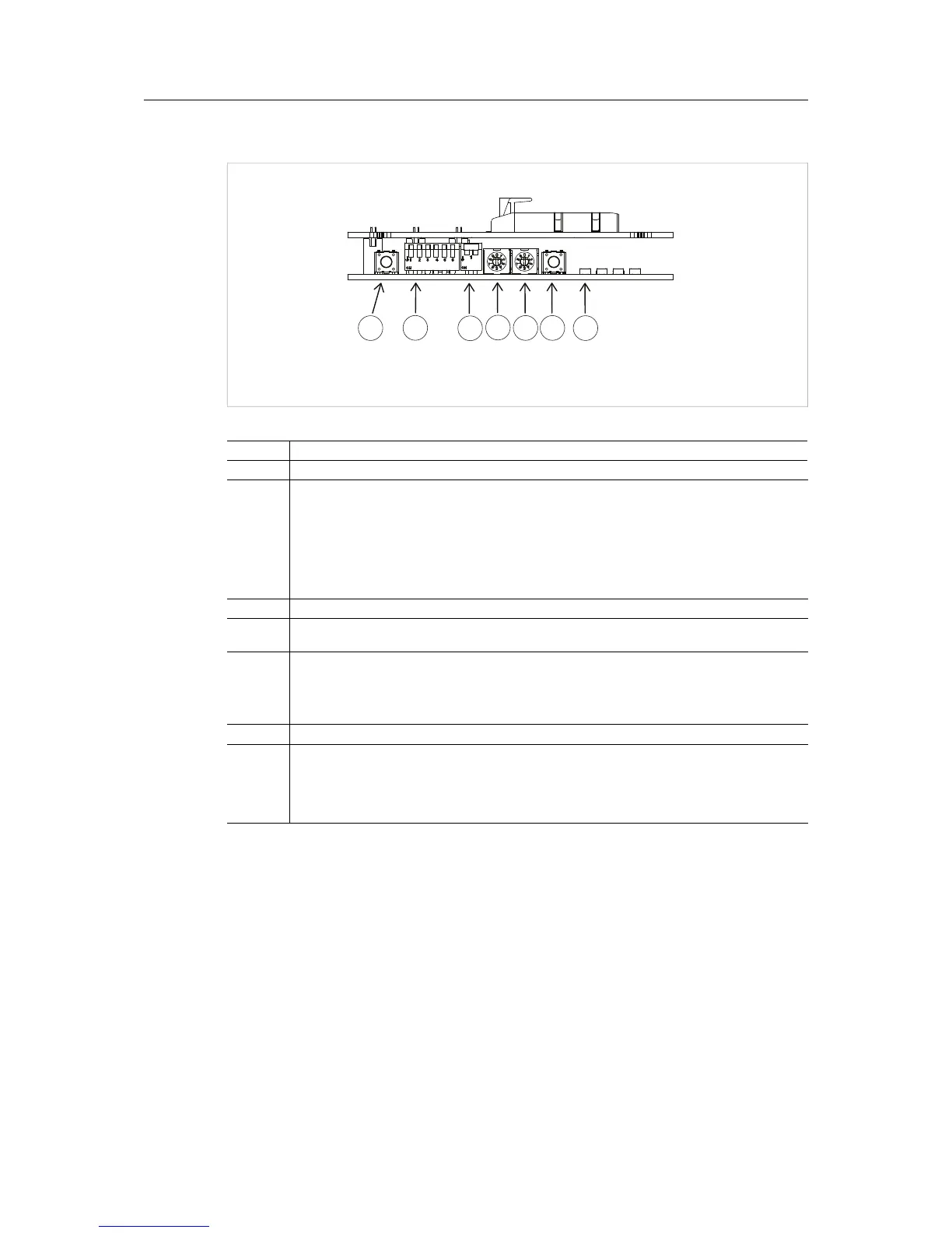
No. Description
1 Reset button. Software reset of the development board.
2 Control Switch
Leave all switches in off position for normal operation.
1: Power to the Anybus CompactCom module. If this switch is on, the module is pow-
ered, whether or not the PC has established a path to the module.
2: On: Reset release for the Anybus CompactCom module, overriding software reset.
The operating mode is set to [0,0,0,0] (OM[0.. 3]).
3 - 6: (not used)
3 Reserved. Must always be ON
4 Mode switch. Should always be set to 1 (USB2 to module mode).
The bevelled side of the switch should be pointed towards the chosen number.
5
ID switch. Defines which path is used for communication. The switch can have any value at startup.
Once a path is established, the value of the switch is connected to the path and should not be
changed. If more than one USB board are connected to a PC, each board must have a uinque ID
setting.
The bevelled side of the switch should be pointed towards the chosen number.
6 (not used)
7
Dual color LEDs. Only the LED to the left is used.
Off No power to the Anybus CompactCom module
Green Power on or Control Switch 1 is on (see no. 2 above)
Red Power off, path closed correctly
Anybus