EasyManuals Logo

Anybus CompactCom User Manual

Anybus CompactCom
22 pages
To Next Page IconTo Next Page
To Previous Page IconTo Previous Page
Page #14 background imageLoading...
Page #14 background image
Description 12 (20)
Header Signal
Name
Printed on
Board
Signal Name
Serial Mode Shift
Register
SPI Mode 8-bit Mode 16-bit Mode
JP8
Rx
Tx
MI0
MI1
MD0
(NC)
(NC)
(NC)
RX RX ASM RX ASM RX ASM RX ASM RX
TX TX / OM3 ASM TX /
OM3
ASM TX /
OM3
ASM TX /
OM3
ASM TX /
OM3
MI0 MI0 MI0 MI0/SYNC MI0/SYNC MI0/SYNC
MI1 MI1 MI1 MI1 MI1 MI1
MD0 MD0 MD0 MD0 MD0 MD0
(NC)
(NC)
(NC)
Please refer to the Anybus CompactCom M40/M30 Hardware Design Guide for more
information.
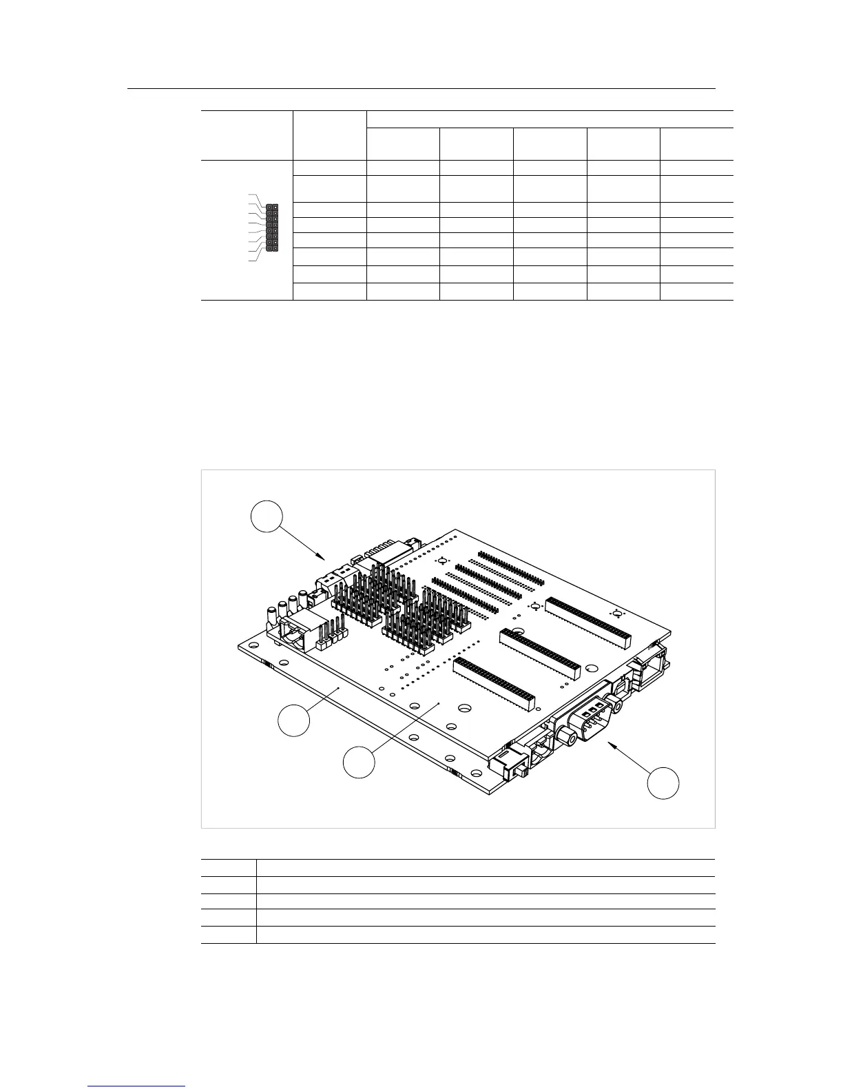
3.4 Option Board Overview (Brick)
The option board for brick provides in-circuit access to all signals of the Anybus CompactCom
host interface, allowing in-circuit debugging and evaluation capacities.
The option board operates at 3.3 VDC.
3
4
2
1
Fig. 5
No Description
1 Brick adaptor card
2 USB base board
3 See Connectors, p. 8.
4 See Control Switches, p. 9.
Anybus
®
CompactCom Starter Kit Reference Guide HMSI-27-224 2.0

Questions and Answers:

Question and Answer IconNeed help?

Do you have a question about the Anybus CompactCom and is the answer not in the manual?

Anybus CompactCom Specifications

General IconGeneral
BrandAnybus
ModelCompactCom
CategoryControl Unit
LanguageEnglish

Related product manuals