Description 7 (20)
3 Description
3.1 General Information
The starter kit package includes a development board, which can be used to develop network-
ing applications via the host interface channels of the Anybus CompactCom module. Depend-
ing on selected starter kit , the kit includes either an option board for Anybus CompactCom
M40/M30 (module) or Anybus CompactCom B40 (brick).
The development board connects to a standard USB2 port, and operates at 24 V ±20%.
The Anybus CompactCom B40 option board as well as the expansion board, included with the
Anybus CompactCom M40/M30 option board, both provide in-circuit access to all signals of the
Anybus CompactCom host interface, allowing in-circuit debugging and evaluation capacities.
These boards operate at 3.3 VDC.
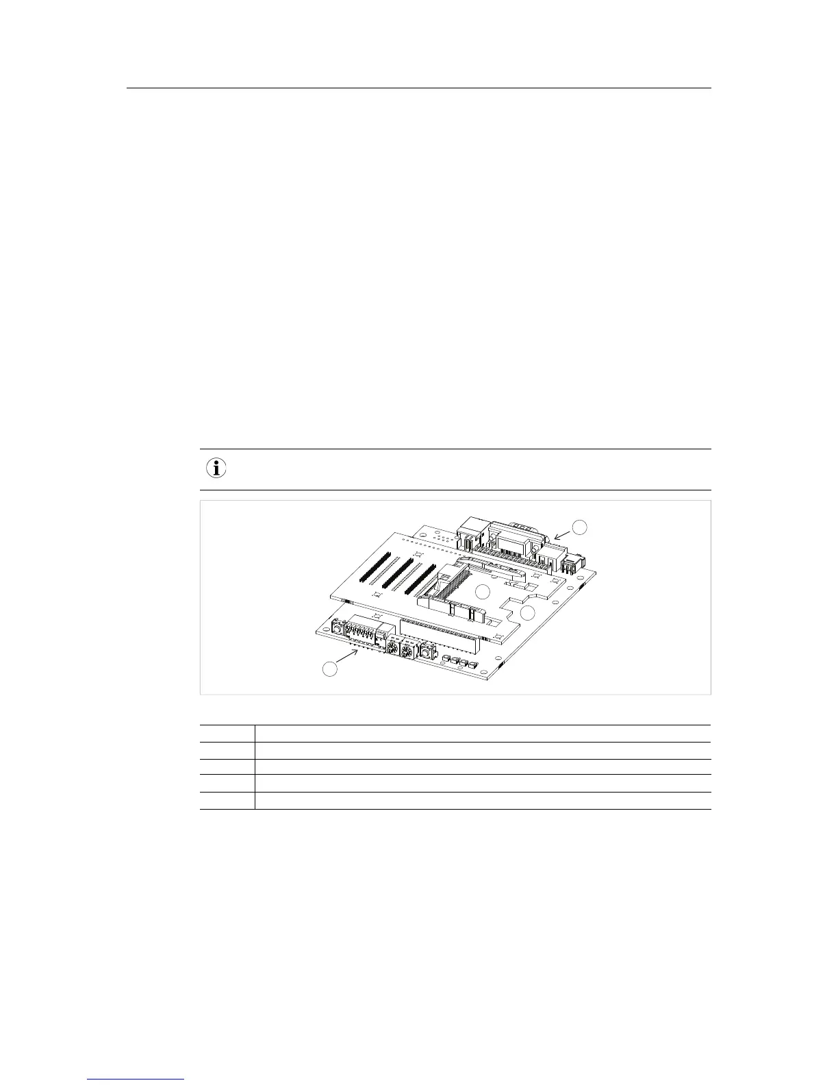
3.2 Option Board Overview (Module)
The starter kit holds two PCBs joined as shown in the picture. An optional module, with or with-
out housing, or an expansion board (see Expansion Board Overview, p. 10), can be connected
to the top board (1).
All three contacts have to be joined as shown for correct functionality. Any other position of the
upper PCB will result in the starter kit not working.