Description 16 (20)
3.4.3 Host Interface Signals
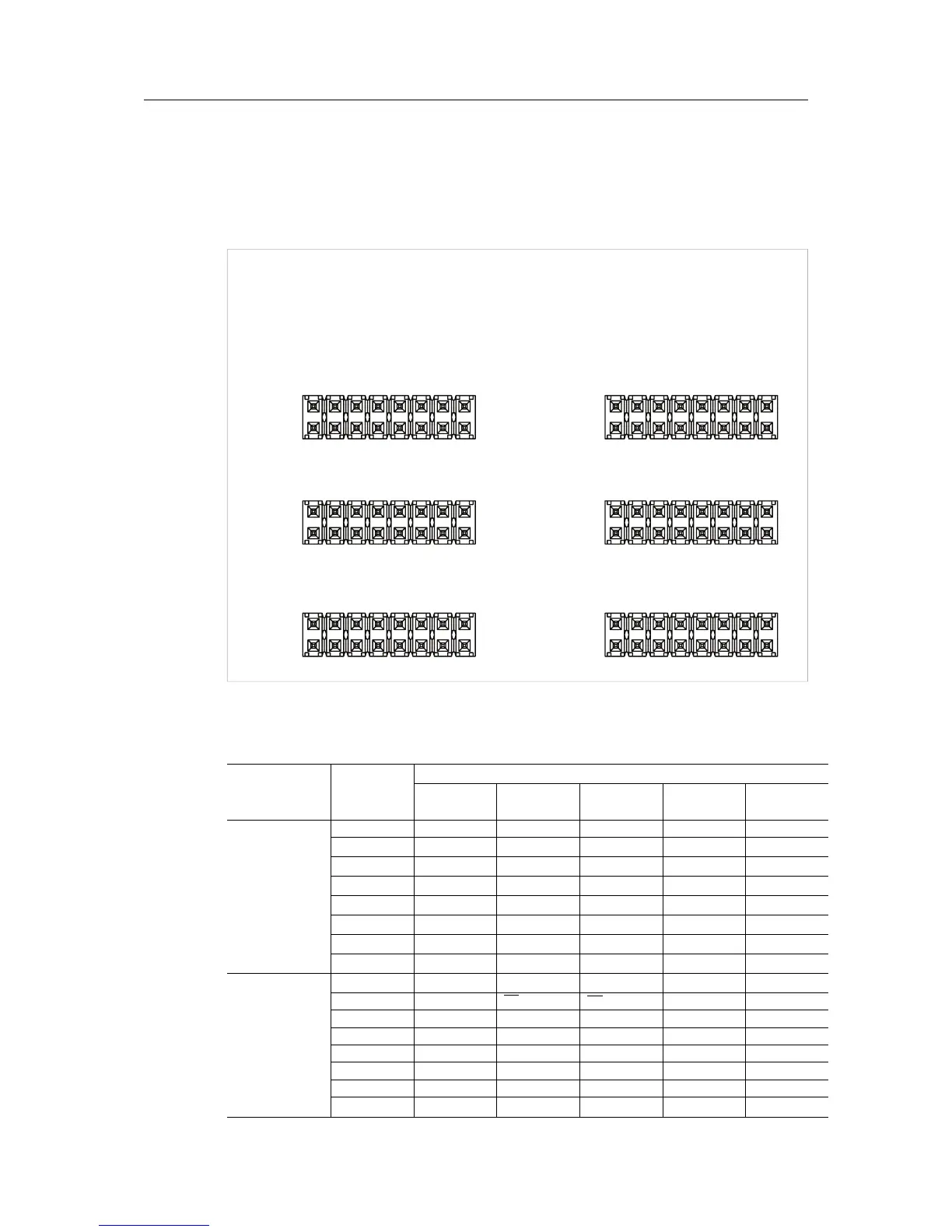
The Anybus CompactCom host interface signals are available through six 16-pin headers (2.54
mm).
• The lower row of each header is connected to signal ground.
• The upper row of each header holds the host interface signals.
Depending on operating mode, the pins have different names and different functionality. Pre-
sented below is an overview of all pins.
Header Signal
Name
Printed on
Board
Signal Name
Serial Mode Shift
Register
SPI Mode 8-bit Mode 16-bit Mode
JP18 IOC2 MD0 MD0 MD0 MD0 MD0
A0 DIP1_0 DIP1_0 DIP1_0 A0 WEH
A1 DIP1_1 DIP1_1 DIP1_1 A1 A1
A2 DIP1_2 DIP1_2 DIP1_2 A2 A2
A3 DIP1_3 DIP1_3 DIP1_3 A3 A3
A4 DIP1_4 DIP1_4 DIP1_4 A4 A4
A5 DIP1_5 DIP1_5 DIP1_5 A5 A5
A6 DIP1_6 DIP1_6 DIP1_6 A6 A6
JP19 A7 DIP1_7 DIP1_7 DIP1_7 A7 A7
A8 LD SS A8 A8
A9 SCLK SCLK A9 A9
A10 DO MISO A10 A10
A11 DI MOSI A11 A11
A12 ASM RX A12 A12
A13 ASM TX A13 A13
(NC)
Anybus
®
CompactCom Starter Kit Reference Guide HMSI-27-224 2.0