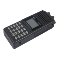
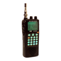
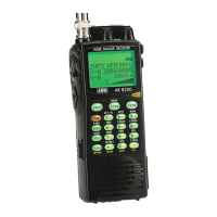
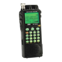
AR8000 operating manual
43
attenuator is OFF.
The selection of attenuator may also be programmed into memory channels
and when defining program search.
Please refer to sections 4-5, 22 & 23 of this manual for further information
regarding aerial suitability, and filters.
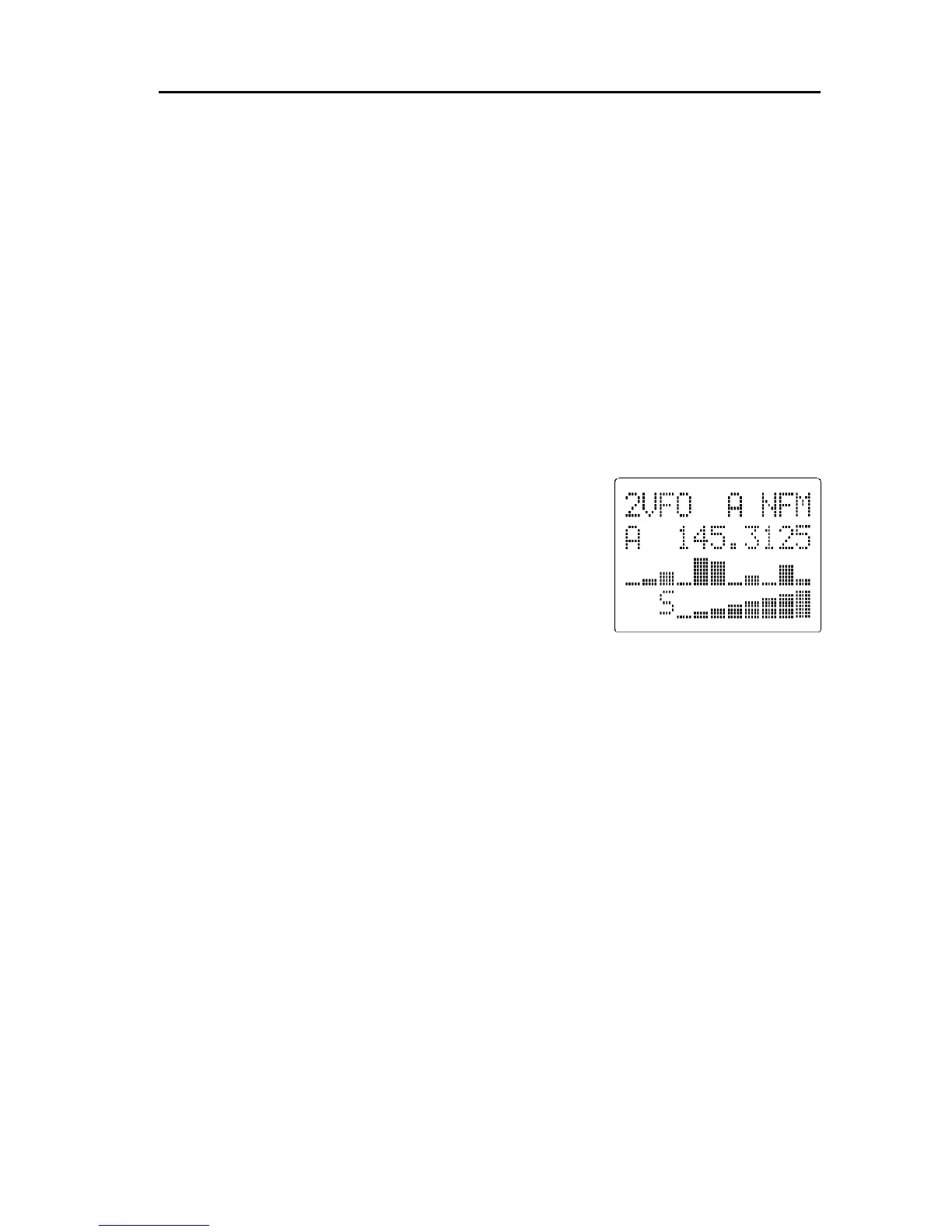
6-13 [B SCP] band scope operation
A band scope facility has been provided so that adjacent channels can be
monitored graphically for activity.
The band scope may be operated in 1VFO or 2VFO mode but cannot be
used while in scan mode, search mode or when priority (PRI CH “P”) is
engaged (switched on). If using 2VFO mode, the stand-by (lower) frequency
will be replaced by the bar graph during band scope operation.
If the sequence [FUNC] [7] is keyed while in VFO
mode, the BAND SCOPE will be activated to check
for adjacent channel occupancy.
The band scope facility produces a bar graph
(sometimes referred to a as spectrum or panoramic -
pan display). The bar graph uses the whole eleven
horizontal positions of the third line of the LCD (five
channels either side of the centre frequency). The
stronger the signal then the higher the bar graph.
The first (lowest) segment of each bar is displayed even if no signals are
present so that band scope operation is confirmed at a glance.
Note: It is possible that false signal levels may appear on the band scope
due to local noise or the close proximity of computer systems.
The band scope facility is NOT designed to provide accurate spectrum
analyser displays, a purpose built test instrument is required for
specialist measurement applications.
The band scope channel spacing is determined by the receive mode (NFM,
USB etc). The active VFO frequency is positioned in the centre of the
display with five adjacent channels above and below the centre frequency
to each side. SET OFFSET channels may be displayed if the facility is
engaged.
The minimum spacing between each adjacent channel is 3 kHz on USB, LSB &
CW and 10 kHz on NFM & AM.
When the [DIAL] is turned or every five seconds the display will be updated.
This can be a useful feature if the “exact” frequency of a specific service is not
known. There will be a brief interruption to the active monitored station
(centre frequency) every five seconds as the AR8000 scans adjacent channels
to update the display.