8
PREPARATION
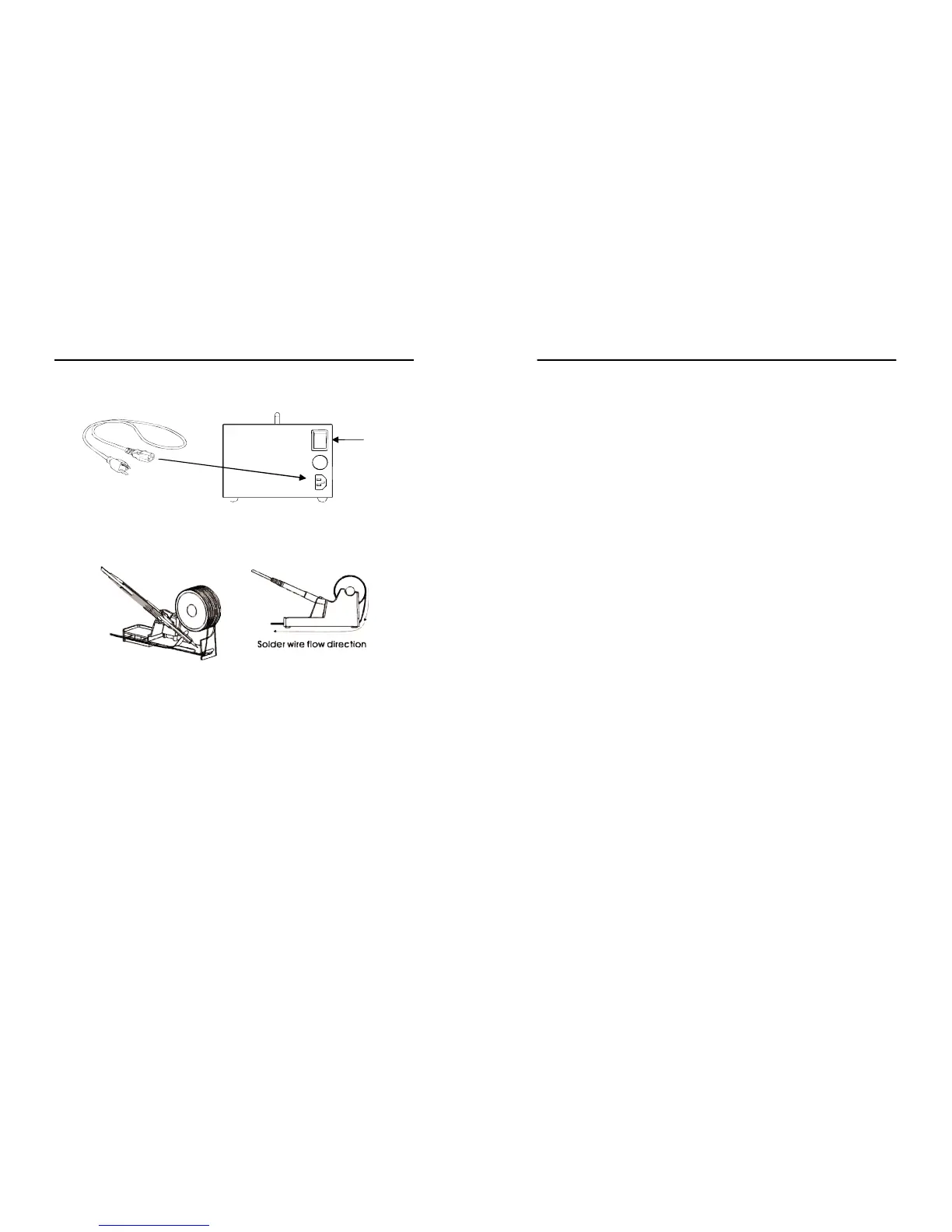
A.MainPower
1.Plugpowercordintoreceptaclefoundatthebackoftheunit.
2.SwitchonthemainpowerswitchtoturnunitON.
B.SolderingIron
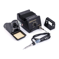
1.Installsolderwiretothesolderironholder(seeFigure1).
2.Attachthesolderingirontothemainunitviathe5pinoutput
terminal,D1,foundattheleftsideofthecontrolpanel.
3.Placethesolderingirontothesolderingironstandasshown
inFigure1.
C.SmokeAbsorber
Attachthesmoke absorbingpen tothe smokeabsorberoutput
terminal, D2, on the control panel. Make sure that the cord
connectionsarefreefromanytangles.
D.HotAirGun
Placethehotairguninthestandtoprepareforusage.
Figure 1. Soldering Iron stand with solder wire holder
Power
Switch
13
OPERATINGGUIDELINES
● The soldering iron display A2 will turn to “##” or “0##” ,
indicatingitisnowondigitalcalibrationmode.
● Turn the soldering iron adjustment knob to set calibration to “
00”.Thisresetsthecalibrationtozero.
● letsystemsavethecalibrationvalueintothememory.
3. Setsolderingirontodesiredworkingtemperature.
4. Wait a few minutes for the temperature to stabilize before
checking the temperature difference with an external calibrated
probe.
5. If external calibrated probe shows a higher number than the
968A+ soldering iron displayed actual temperature we input a
positive calibration number. If external calibratedprobe shows a
lower number than the displayed 968A+ soldering iron actual
temperatureweinputanegativecalibrationnumber.
6. Againaccessthecalibrationmodeofthesolderingiron:
● EnsurethattheSMDandSmokeabsorberfunctionswitchisoff.
● EnsurethatSolderingironfunctionswitchison.
● PressandholdthehotairtemperatureincreasebuttonA6.
● The soldering iron display A2 will turn to “##” or “0##” ,
indicatingitisnowondigitalcalibrationmode.
● Turn the soldering iron adjustment knob to set the desired
calibrationvalue.
● Letsystemsavethedesiredcalibrationvalueintothememory.
7. Calibrationnumberscanbeadjustedfromnegative50topositive
50.Ifthedigitalcalibrationnumberisinsufficientforcalibration.
Themanualcalibrationoptionisavailableformacroadjustments