10
OPERATING PROCEDURES
4. Press the increase or decrease button to adjust the bottom heater set
temperaturelevel.Thesettemperatureisadjustablefrom50to280Cinthis
typeofoperation.Totemporarilyturnoffthebottomheatersimultaneously
pressboththe“Increase”and“decrease”button
(#3  fromthecontrol
paneldisplayseepage8)
.Thebottomdisplaywillshow“OFF”indicatingthe
bottomheaterisnowturnedoff.
5. To view the actual internal temperature read by the Top heater and the
bottomheater’sinternal temperature probe, repeatedly press the selection
buttonuntilthetopdisplayshowstheactualvalueofthetopheaterinternal
temperaturefollowedbyasuffix“d”.Thenumberdisplayedinthemiddlerow
followedbyasuffix“E”isforthebottomheateractualinternaltemperature.
Thebottomdisplayshowstheactualtemperatureofthesolderingiron,itis
followedbyasuffix“F”.
6. To view the actual temperature read by the three external temperature
sensor,repeatedlypresstheselectionbuttonuntilthetopdisplayshowsthe
top heater external temperature prob’s actual temperature followed by a
suffix “A”. The middle display will show external temperature probe b’s
actual measured temperature followed by a suffix “b”. And the bottom
display would show the actual measured temperature of the external
temperatureprobeC.Itisfollowedbyasuffix“C”.
Note:Externaltemperatureprobesarelabeled.Topheaterexternalprobe
islabeledA,whiletheothertwoislabeledbandC.Thedisplayedactual
temperaturereading’ssuffixcorrespondstothelabels.
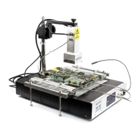
E.TYPE“1”OPERATION
Before proceeding with this type of operation, attach the top external
temperatureprobe A toonecorneroftheBGAorICtobereworked.Thenattaché
theexternaltemperatureprobe b totheundersideofthePCBtobeworkedon,
preferably not near the are of the BGA or IC to be reworked on but not directly
underneaththeBGAorIC..Theexternaltemperatureprobe Ccanbeplacednear
anyareaofinterest.
7
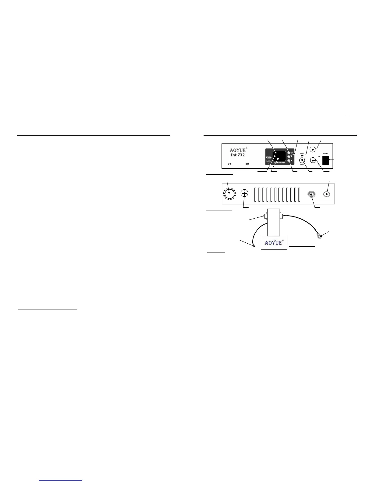
LEGEND:
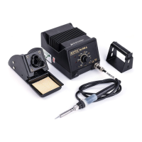
1—DigitalDisplay 7—SolderIronConnector
1.aTopDisplay 8—MainPowerSwitch.
1.bMiddleDisplay 9—PowerCord.
1.cBottomDisplay 10—FuseHolder.
2—SelectionButton 11— TopHeaterPowerCord
3—IncreaseButton/EnterButton 12— TopHeaterSensorConnector
4—DecreaseButton 13— TopHeaterPowerConnector
5—StatusLED 14— TopHeaterSensorCord
6—ExternalSensorConnector 15— TopHeaterExternalSensor
***(Expansionforfutureversions,Maynotbeavailableforcurrentreleases)16— LampAttachment.***
Suffixguide:
A - ActualTemperatureofSensor“A”/SetTemperatureofTopHeater.
b - ActualTemperatureofSensor“b”/SetTemperatureofBottomHeater.
c - ActualTemperatureofSensor“c”.
D - ActualTemperatureofTopHeaterInternalSensor.
E - ActualTemperatureofBottomheaterInternalSensor.
F - Set/ActualTemperatureofSolderIron.
1.a
4
32
6
8
5
FrontPanel
BackPanel
11
12
1.b 1.c 7
10
9
13
14
15
16
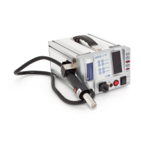
CONTROL PANEL GUIDE
TopHeater
 Loading...