Appendix – UPS Components and Options
40 Smart-UPS® VT 10-30 kVA, 208/220 V and XR Battery Enclosure Operation Manual 990-1599B
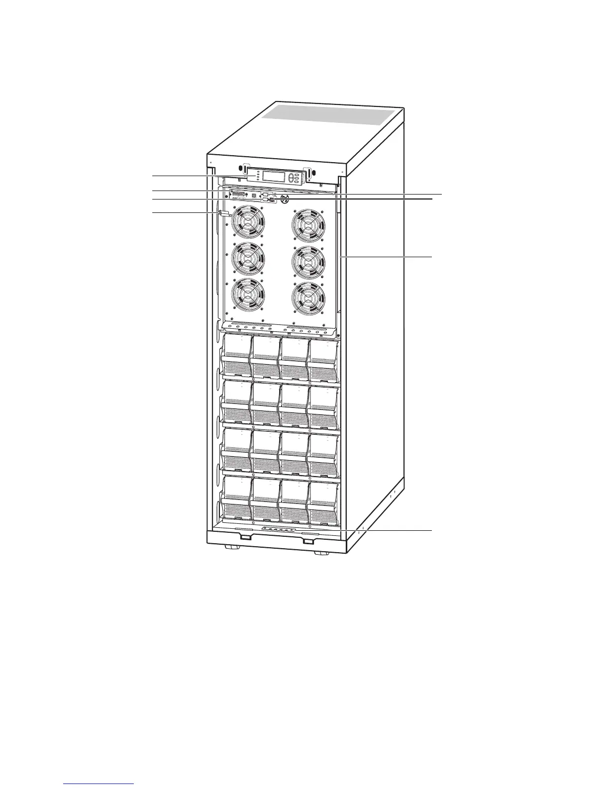
User interface
Display: user-control interface used to configure the functionality, monitor the system, set alarm
thresholds, and to provide audible and visual alarms.
Network Management Card with Environmental Monitor (AP9619): used for remote system
control and monitoring, e-mail notifications etc.
Computer-interface port for the connection of computers with APC Powerchute
®
software.
Mechanical Bypass Lever: used to bypass the upstream mains power around the UPS to support
the load directly = internal mechanical bypass operation.
Service port (for APC maintenance personnel only).
10
/10
0
B
as
e
-T
P
ro
b
e
A
P
9
6
1
9
N
e
tw
o
r
k
M
a
n
a
g
e
m
e
n
t
C
a
r
d
E
M
!
R
e
se
t
O
u
tp
ut
Pw
r
Z
o
ne
1
0
/1
00
M
o
d
e
l
:
Serial:
BATTERY UNIT
M
o
d
e
l:
Serial:
BATTERY UNIT
M
o
d
e
l:
Serial:
BATTERY UNIT
M
o
d
e
l:
Serial:
BATTERY UNIT
M
o
d
e
l:
Serial:
BATTERY UNIT
M
o
d
e
l:
Serial:
BATTERY UNIT
M
o
d
e
l:
Serial:
BATTERY UNIT
M
o
d
e
l:
Serial:
BATTERY UNIT
M
o
d
e
l:
Serial:
BATTERY UNIT
M
o
d
e
l:
Serial:
BATTERY UNIT
M
o
d
e
l:
Serial:
BATTERY UNIT
M
o
d
e
l:
Serial:
BATTERY UNIT
M
o
d
e
l:
Serial:
BATTERY UNIT
M
o
d
e
l:
Serial:
BATTERY UNIT
M
o
d
e
l:
Serial:
BATTERY UNIT
M
o
d
e
l:
Serial:
BATTERY UNIT