4
4. Do not locate unit where it or its connections (including the drain and overflow lines) will ever be subjected
to room temperatures under 34° F.
5. The use of resin cleaners in an unvented enclosure is not recommended.
6. INLET/OUTLET PLUMBING: Connect to a supply line downstream of outdoor spigots. Install an inlet shutoff
valve and plumb to the unit’s bypass valve inlet located at the right rear as you face the unit. When assem-
bling the installation fitting package (inlet and outlet), connect the fitting to the plumbing system first and then
attach the nut, split ring and o-ring. Heat from soldering or solvent cements may damage the nut, split ring
or o-ring. Solder joints should be cool and solvent cements should be set before installing the nut, split
ring and o-ring. Avoid getting solder flux, primer, and solvent cement on any part of the o-ring, split ring,
bypass valve or control valve. If the building’s electrical system is grounded to the plumbing, install a copper
grounding strap from the inlet to the outlet pipe. Plumbing must be done in accordance with all
applicable
local codes.
7. DRAIN LINE: First, be sure that the drain can handle the backwash rate of the system. Solder joints near
the drain must be done prior to connecting the drain line flow control fitting. Leave at least 6" between the
drain line flow control fitting and solder joints. Failure to do this could cause interior damage to the flow
control. Install a ½” I.D. flexible plastic tube to the Drain Line Assembly or discard the tubing nut and use the
¾” NPT fitting for rigid pipe. If the backwash rate is greater than 7 gpm, use a ¾” drain line. Where the
drain line is elevated but empties into a drain below the level of the control valve, form a 7" loop at the dis-
charge end of the line so that the bottom of the loop is level with the drain connection on the control valve.
This will provide an adequate antisiphon trap. Where the drain empties into an overhead sewer line, a sink-
type trap must be used. Run drain tube to its discharge point in accordance with plumbing codes. Pay special
attention to codes for air gaps and anti-siphon devices.
8. BRINE TANK CONNECTION: Install a 3/8’’ O.D. polyethylene tube from the Refill Elbow to the Brine Valve
in the brine tank.
PLEASE NOTE: After installing salt into the brine tank, please fill water into the brine tank up to
a little above salt level.
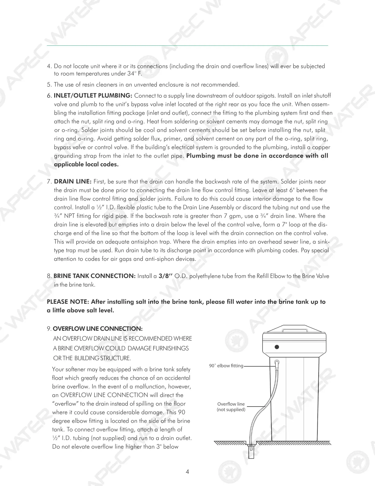
9. OVERFLOW LINE CONNECTION:
AN OVERFLOW DRAIN LINE IS RECOMMENDED WHERE
A BRINE OVERFLOW COULD DAMAGE FURNISHINGS
OR THE BUILDING STRUCTURE.
Your softener may be equipped with a brine tank safety
float which greatly reduces the chance of an accidental
brine overflow. In the event of a malfunction, however,
an OVERFLOW LINE CONNECTION will direct the
“overflow” to the drain instead of spilling on the floor
where it could cause considerable damage. This 90
degree elbow fitting is located on the side of the brine
tank. To connect overflow fitting, attach a length of
½” I.D. tubing (not supplied) and run to a drain outlet.
Do not elevate overflow line higher than 3" below
Overflow line
(not supplied)
90˚ elbow fitting
 Loading...