30
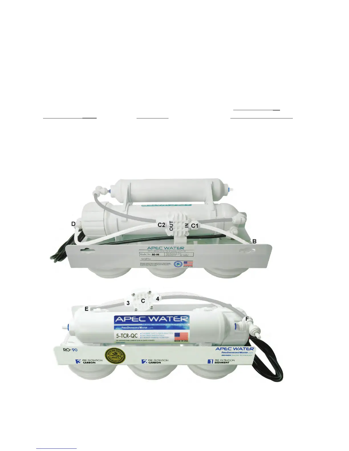
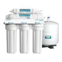
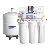
Fig. 18A
Back View
Fig. 18B
Front View
- Output line is crimped —> Remove crimp
- Incorrect installation —> See Fig.11 & 11A. Verify all line connections.
- Tank defective, no pre-charge pressure —> Set tank pre-charge to 5-7 psi.
- ASO connection Error —> See Fig. 18A and Fig. 18B to reconnect ASO to the correct
connection.
The ASO valve has 4 lines connected to it, 2 Whites and 2 Clears. C1 is labeled IN and
C2 is labeled OUT on the valve. C3 and C4 are connected to the ends with the 4 screws.
Please confirm connections:
• Stage 3 Carbon: White tubing (point B) is connected to C1 (IN) fig.18A
• Membrane: White tubing (point D) is connected to C2 (OUT) fig.18A
• Check Valve: Clear tubing (point E) is connected to C3 fig.18B
• 5th stage Tee inlet: Clear tubing (point F) is connected to C4 fig.18B