9
''! -#"( ##&
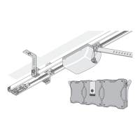
Refer to the illustrations 1 – 4 to check which type of door you have.
1) Sectional door No accessories required
with single track Sectional door fitting with boomerang
recommended
with double track Sectional door fitting without boomerang
recommended
2) Up-and-over, tracked doors No accessories required
3) Up-and-over, canopy door Curved arm required as accessory
4) Hinged double doors Wing door fitting required as accessory
Parts shown in picture:
• Lay out all the parts as shown (the control unit () is inside the garage)
and have tools to hand.
• The chain must be fully clipped into the chain cover at all times.
!$#&("(!/93AC@3B6/B/::>/@BA=4B6316/7<:=19/@3
>CA632B=53B63@A=B6/BB63G/@34:CA6(6316/7<1=D3@7A<=B
>/19/57<5=<=B@3;=D37B
• Slide the carriage () with chain onto one of the tracks (), making sure
that the contact springs are in position. Slide the other two tracks ()
onto the track joints () as far as they will go. You now have a single
continuous track.
• Push the red switch marked "H" () into the track with the tip point ing
towards the carriage ().
• Push the chain through the opening in the switch ().
• Insert the screws (/) into the ceiling holder (0).
• Mount the steel brackets (1) on the ceiling holder (0) as shown,
using nuts (2) and tooth lock washers (3).
• Slide the ceiling holder (0) onto the track from the rear.
• Connect the chain to the bolt on the control unit () using the chain lock
(). Slide the control unit onto the track () from the rear as far as it will
go.
!$#&("((63E7@7<55@=;;3B;CAB03=<B630=BB=;=4B63
1=<B@=:C<7B
/ Slide the red switch marked "V" () onto the other end of the track.
0 Fit the tensioning element (/) into the chain and
1 turn 90°.
2 Slide the plug-in unit () onto the track () and push the tensioning ele-
ment (/) through it. Put the washer (0) and spring (1) on the
tensioning screw (2) and screw it into the tensioning element (14a).
• Tighten the chain as far as the mark (arrow).
• Screw the two steel brackets (/) to the plug-in part () using the
screw (0) and nut (1), but do not yet tighten fully.
• If the carriage () will not move, disengage it by pulling the emergency
release () once.
• Mount the door fitting (/) and connecting arm (0) on the carriage
() as shown, using the bolt 1 and retaining clip (2).
"'( "(#$&(#&#"(&
"
• Turn the whole assembled unit so that the opening in the track is facing
downwards. Unlock the door and remove all of the door locks and cords
so that they cannot interfere with the door’s movement.
• Make sure that the garage door runs smoothly in both directions. The
door must be balanced, and should stay in any position. If required, the
door should be adjusted before the assembled operator is fitted.
• Measure the centre of the door at the top and mark it on the face of the
door and also on the lintel above the door.
• Open the door slowly and note where the top edge comes closest to the
ceiling (including the rubber strip, where fitted). This point (the highest
running point of the door) must be at least 40 mm from the ceiling.
The distance between the highest running point of the door and the bot-
tom edge of the C-track must be at least 5 mm and no more than 65 mm.
"#((63/@;;CAB03/B/;/F/<5:3=4`
• Close the door.
• Depending on the space available the operator can be mounted on the
lintel (frame) or the ceiling (as close to the lintel as possible). Mark and
drill holes 74 mm to the right and left of the middle of the door and
20 – 50 mm above the highest running point of the door (10 mm
diameter holes for concrete, 5 mm diameter for wood).
!$#&("((/93B63B6719<3AA=4B63:7<B3:=@137:7<57<B=
1=<A723@/B7=<(/931/@3<=BB=2/;/53B631=<B@=:C<7B
• Insert plugs (2) (if necessary), raise the operator at the front and
secure the steel brackets (/) using the wood screws (4) and
washers (3).
• Raise the operator at the rear and rest it on a ladder.
• Push the carriage backwards. The gap between the control unit () and
the ceiling bracket (1) can be adjusted to anything between
0 – 600 mm depend ing on the particular garage ceiling. Adjust the ceil-
ing bracket (1) vertically to ensure that the door does not touch the
C-track () when it is running and align the operator with the centre of
the door at the same time. Mark the holes and drill (in concrete 10 mm
dia meter, in wood 5 mm diameter). Insert plugs (4) and secure the
steel brackets (1) with the screws (6) and washers (5).
!$#&("((/93B63B6719<3AA=4B63137:7<57<B=1=<A723@/B7=<
• If required, the projecting ends of the steel brackets (1) can be cut off
with a hacksaw.
• Close the door. Fully tighten the screw (0) and the nut (1). Slide
the carriage () forward towards the lintel. Hold the door bracket (/)
in position on the door and centre it. The bracket can be fitted to the
door fitting in a variety of ways, depending on the type of door. Predrill 5
mm diameter holes. Secure the door fitting (/) with the four screws
(3). If required, other screws than those supplied may have to be
used to ensure that the bracket is secure.
• The operator must not stand in the way of the door when activating the
switch. The operator must have a clear view of the door. Do not install
the switch in the way of the door. Install the wall switch () in a suitable
location, at least 1.6 m above floor level.
Lay the two-core cable and connect the white and brown wires up to the
wall switch ().
!$#&("("3D3@7<AB/::B63AE7B161/0:3/:=<5A723/>=E3@
1/0:3B67A1/<1/CA34/C:BAB==11C@
!
• Install the wall socket.
• Install the socket on the ceiling at a maximum of 0.5 m away from the
control unit.
"#(#0A3@D3/::/>>:71/0:3*@35C:/B7=<A
"
• Slide switch "V" () right up to the carriage (), until the quiet click of
the switch is audible and then tighten the tensioning screw. Open the
door fully.
• Slide switch "H" () right up to the carriage (), until the quiet click of the
switch is audible and then tighten the tensioning screw. Engage the car-
riage () by pulling the emergency release () once.
1 Carriage with chain and chain
cover
2 C-track, 3 pcs
3 Track joints, 2 pcs
4 Control unit with lamp
5 Chain lock, 3-part
6 Mains power cable
7 Wall switch cable
8 Wall switch
9 Rear limit switch, marked "H"
10 Front limit switch, marked "V"
11 Ceiling holder
12 Connecting arm, door fitting,
bolt, retaining clip, screws
13 Plug-in unit
14 Tensioning element, washer,
spring, tensioning screw
15 Steel brackets, screws, plugs,
washers, nuts
16 Emergency release
17 Lamp cover
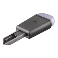
18 Transmitter
 Loading...