10
"( #$&(#"
#
• Plug in the mains cable (). The light must flash. (If the light fails to flash,
refer to the section on "Cancelling power values"). To allow it to "learn"
the correct power values, the operator must go through two full opening
and closing cycles for it to register the required power for both directions.
To start the operator, press the wall switch () or the transmitter ().
The integrat ed light flashes during learning. The light only remains on
permanently when the required power has been learnt for both direc-
tions.
• Check the end position by opening and closing the door. If necessary,
readjust the limit switches (/) until the door opens and closes fully.
%
• Check that the operator can be stopped when opening and closing by
pressing your hand lightly against the middle of the door at a height of
at least 1 m above floor level. If it stops when closing, the operator re-
tracts the door about 100 mm.
!$#&("( /@/53AE7B6=<:G=<3>=7<B=43<B@G;CAB0347B
B32E7B6/0=E23<1/0:34=@3;3@53<1GC<:=197<54@=;B63=CB
A72374B63@37A/>=E3@4/7:C@34/A:7>2==@7AA3B7<B=B632==@
/A:7>2==@A/43BG23D713;CAB037<AB/::32
*#$&(#"
$
3:3B7<5>=E3@D/:C3A
• Once the operator has been installed and connected up to the mains
supply, the integrated light flashes indicating that the operator has still
not "learned" any power values. If the light fails to flash because the op-
erator has already learned power values – e.g. during no-load dummy
runs – these values must first be deleted.
• Prise off lamp cover () with a screwdriver. Using a narrow-pointed ob-
ject, hold down the button () (marked "T1") for approx. 5 seconds. As
soon as the power values are deleted, the light goes out. To program
the power values, proceed as described under #. Fit lamp cover ().
$
Changing the bulb in the control unit
• Unplug the mains cable () and unclip the lamp cover () using a
screwdriver. Unscrew the bulb () by turning it anticlockwise.
• Screw in a new bulb () by turning it clockwise as far as it will go (32.5
V, 34 W, BA 15s).
• Dispose of old bulb in an environmentally friendly manner.
&
$@=5@/;;7<5B63B@/<A;7BB3@
"#((63A31=<2@/27=16/<<3:7A=<:G<332324=@>/@B7/:=>3<7<5
=@16/<<3:=>3@/B7=<
'3?C3<13
• Press the program button () on the operator/receiver
- for channel 1, repeatedly until LED () lights up; release button
- for channel 2, repeatedly until LED () lights up; release button
If no radio command is transmitted within 10 sec., the receiver reverts
to the normal mode.
• Press desired transmitter button within range of the receiver. The
transmitter sends the radio command to the operator/radio receiver.
- depending on which channel was selected, LED () or LED ()
goes out.
• The above two steps must be repeated for every additional transmitter
to be programmed for this operator/receiver. Up to 112 radio commands
can be stored, whereby each radio channel takes up one position in the
memory.
F/;>:3
- If only one button on each of a number of transmitters is
programmed, a total of 112 transmitters can be stored.
- If two buttons on each of a number of transmitters are programmed,
there is only space for 56 transmitters.
• The learning mode can be interrupted by pressing the program button
() repeatedly until all LEDs go out.
&
+7>7<5B63@3137D3@;3;=@G
If a remote control is lost, for security reasons the receiver memory must
be wiped and all transmitters reprogrammed.
'3?C3<13
• Press and hold program key ()
• LED ( or ) lights up for 5 sec., then flashes for 10 sec. and then
lights steadily again.
• 10 sec. later (25 sec. in total) both LEDs light up - this means all radio
channels have been wiped.
• Release program button (); the LEDs go out; the wiping process is
complete.
&
3:3B7<5/@/27=16/<<3:4@=;B63@/27=@3137D3@
=@@/27=16/<<3:
• Press and hold program button ().
• LED () lights up for 5 sec., then flashes for 10 sec.
• As soon as LED () lights up again, release the program button ();
the LED goes out; the deletion process is complete.
=@@/27=16/<<3:
• Press and hold program button ().
• LED () lights up for 5 sec., then flashes for 10 sec.
• As soon as LED () lights up again, release the program button ();
the LED goes out; the deletion process is complete.
&
3:3B7<5/B@/<A;7BB3@0CBB=<4@=;B63@/27=@3137D3@
If a user moves house and would like to take his hand transmitter with
him, all the radio commands of the transmitter must be deleted from the
radio receiver.
!$#&("(=@A31C@7BG@3/A=<A3D3@G0CBB=</<20CBB=<
1=;07</B7=<=<B63B@/<A;7BB3@A6=C:20323:3B32
'3?C3<13
• Press program button () on operator/receiver and hold down for
5 seconds until an LED ( or ) flashes (it does not matter which).
Press the button or button combination on the transmitter, the command
for which you want to delete from the operator/receiver; the LED goes
out; the deletion process is complete.
Repeat the process for all buttons or button combinations to be deleted.
&
6/<57<5B@/<A;7BB3@0/BB3@G
Use a coin to open the transmitter on the keyring. Make sure to insert the
battery the right way round. Remove the battery and replace with a new
one (CR 2032). Note the correct polarity of the battery. Close the battery
cover flap and check function using transmit LED.
(
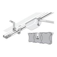
This control offers you extensive additional functions, e.g. partial door
opening, 2-channel operation, door status indicator and an interface to the
TorMinal ().
=<<31B=@
• Permissible cable gauge: max. 1.5 mm²
Pin allocation of the connector:
1 + 2 Transformer, secondary (red)
3 C-track (green)
4 Chain (red)
5 + 6 Switch connection, further switches can be attached in parallel
here
=<<31B7=<=>B7=<A
• Additional connection options on the pluggable screw terminal () of
the control unit.
Permissible cable gauge: max. 0.75 mm².
!$#&("((630@7253/BB3@;7</:;CAB031=<<31B32
E63<3D3@<=A/43BG23D7137A7<AB/::324G=C1=<<31B/A/43BG
23D713B/93=CBB630@7253/BB3@;7</:
CA3
• Fuse (): protection of DC 24 V output (terminals 11 + 12) with 1 A
quick-acting fuse.
(3@;7</: =<<31B7=<=>B7=<A
7
8
Safety connection (light barrier or 2-switch input) delivery status with
bridge
Signal (SIG)
Ground (GND)
9
10
* output regulated, ;/F
+DC 24 V
Ground (GND)
11
12
Connection * warning light C<@35C:/B32;/F*
;/F
+DC 24 V
Ground (GND)

 Loading...