3
BFMM DC4A SBF
Customer Service (704) 841-6000 www.apollovalves.com
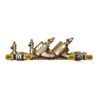
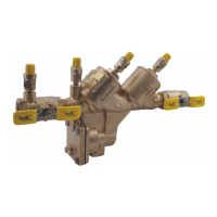
DOUBLE CHECK VALVE BACKFLOW PREVENTER 1/2” 2”
I. DESCRIPTION AND OPERATION
The Double Check Valve (DC) device consists of two independently-acting, spring-loaded check valves. Two resilient seated shut-
o valves and four test cocks complete the assembly. Each check is designed to maintain a minimum of 1 psi across the valve
during normal operation. If at any time the pressure downstream of the device increases above the supply pressure, both check
valves will close to prevent any backow from occurring. The owing and no ow conditions are illustrated in gures 1 and 2.
To initiate ow, supply pressure must be sucient to open both checks and overcome friction, normally a minimum of 3 to 5 psi
above the downstream pressure.
II. INSTALLATION
A. The DC must be installed in an accessible location to facilitate periodic eld testing and maintenance.
B. Flush all upstream piping thoroughly to remove foreign matter prior to installing the device.
C. The device should be installed either horizontally or vertical up for ease of maintenance and testing. A clearance between
the lower most portion of the device and ood grade or oor should be provided for ease of maintenance.
D. When shut-o valves are provided separately, they should be installed with a test cock on the upstream side of the inlet shut-
o valve.
E. After installing the assembly and with downstream or #2 shut-o valve closed, pressurize the device and bleed ALL air
through test cock #4. Then open #2 shut-o valve.