INSTALLATION, OPERATION, & MAINTENANCE MANUAL
www.apollovalves.com Customer Service (704) 841-6000
6
V. TESTING PROCEDURES
This test is performed with the Dierential Pressure Gauge Test Kit. The Dierential Pressure Gauge simply measures the pressure
drop across the check valve. This pressure drop is normally the same as the strength of the check valve spring. In using the
Dierential Pressure Gauge to test the Double Check assembly, a minimum of 1.0 psid is required for each check valve in order
for that check valve to pass the test. Such a small reading is often dicult to read on most test kits. This is one of the drawbacks
of this test. However, since the rst shut-o valve is left in the open position for this test, it is possible to use this test when the
rst shut-o valve is leaking badly.
NOTE: This is a three-valve test kit procedure and may or may not be approved in all jurisdictions. Consult your local water
purveyor for acceptable test procedures.
Test Setup
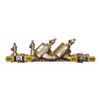
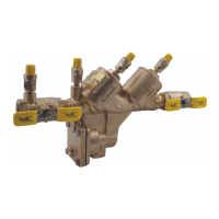
1. Notify customer that the water service will be o. Identify the make, model, and serial number on the backow device.
Inspect that this is an approved assembly - two check valves, two shut-o valves and four test cocks. Observe the area to
make sure there are no leaks.
2. Flush test cocks (1, 2, 3 & 4), then close all test cocks.
3. Install appropriate adapters (if necessary).
4. Close shut-o valve #2.
TEST NO. 1
PURPOSE: To test check valve #1
1. Close all valves on test kit.
2. Connect the high side hose to test cock #2 and the low side hose to test cock #3. Open test cock #2 and test cock #3.
3. Open vent valve “C” and high “A” on the test kit to bleed air from the high side of the kit. Close high “A” valve and then
open low “B” valve to bleed the low side. Close low “B” valve.
4. Record the gauge reading. It must be a minimum of 1.0 psid in order to pass. Close test cock #2 and test cock #3.
TEST NO. 2
PURPOSE: To test check valve #2
1. Move the high side hose to test cock #3 and the low side hose to test cock #4. Open test cock #3 and test cock #4.
2. Open vent “C” valve. Then open high “A” and bleed air from the high side of the kit. Close high “A” valve, and then open low
“B” valve and bleed the low side of the kit. Close low “B” valve.
3. Record the gauge reading. It must be a minimum of 1.0 psid in order to pass. Close test cock #3 and test cock #4. Remove
hoses and test kit. Slowly open shut-o valve #2 in order to restore water ow to the facility, placing the DC back into service.