5
BFMM DC4A SBF
Customer Service (704) 841-6000 www.apollovalves.com
III. TROUBLE SHOOTING
SYMPTOM CAUSE CORRECTIVE ACTION
1. Check valve fails to hold
1 psid.
a. Shut-o valve not closed
completely.
b. Check valve fouled with
debris.
c. Check poppet stem not
moving freely in guide.
a. Close #2 shut-o valve or
inspect for possible
through leakage.
b. Inspect and clean seat
disc and seat.
c. Inspect for debris or
deposit on poppet stem
or guide.
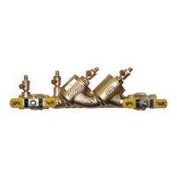
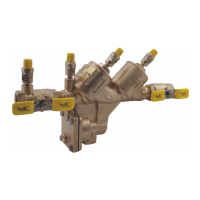
IV. MAINTENANCE INSTRUCTIONS 1/2” – 2”
A. Disassembly - Check Valves
1. Close #2 shut-o valve, then close #1 shut-o valve.
2. Bleed pressure from the assembly by opening #2, #3, and #4 test cocks.
3. Unscrew cap using hex head provided.
4. Push down and turn the spring retainer 90 degrees to remove. Remove the spring. Remove the poppet from the check seat.
5. Normally, the check seat need not be removed. If removal is required, rock it back and forth while pulling outward.
B. Disassembly - Check Valve Poppet
CAUTION: Do not use pliers or other tools, which may damage or scratch the plastic stem.
1. Holding the poppet assembly in one hand, remove screw and retaining washer.
2. Remove the seat disc.
3. All parts should be carefully inspected for any damage or excessive wear and thoroughly rinsed in clean water prior to
reassembly. Replace worn parts as necessary.
C. Assembly - Check Valve Poppet
1. Install new disc in poppet and secure with washer and screw.
D. Assembly - Check Valve
1. If the check seat was removed, install the new o-ring and lubricate with a thin coat of Apollo supplied lubricant, DOW 111
or equal. Line up the seat with the bore and push it rmly into place.
2. Place and center the poppet assembly in the check seat.
3. Install the spring onto the poppet.
4. Install the spring retainer onto the spring by pushing down into the grooves of the check seat and turning 90 degrees.
Ensure spring retainer pops up about .1” and locks into the lugs. CAUTION: Ensure the spring retainer orientation matches
that in the parts list drawing or the device’s ow will be signicantly restricted.
5. Apply a thin coat of Apollo supplied lubricant, DOW 111 or equal on cap o-ring.
6. Install cap.