Apollo 16 Hardware Manual Interconnections 20
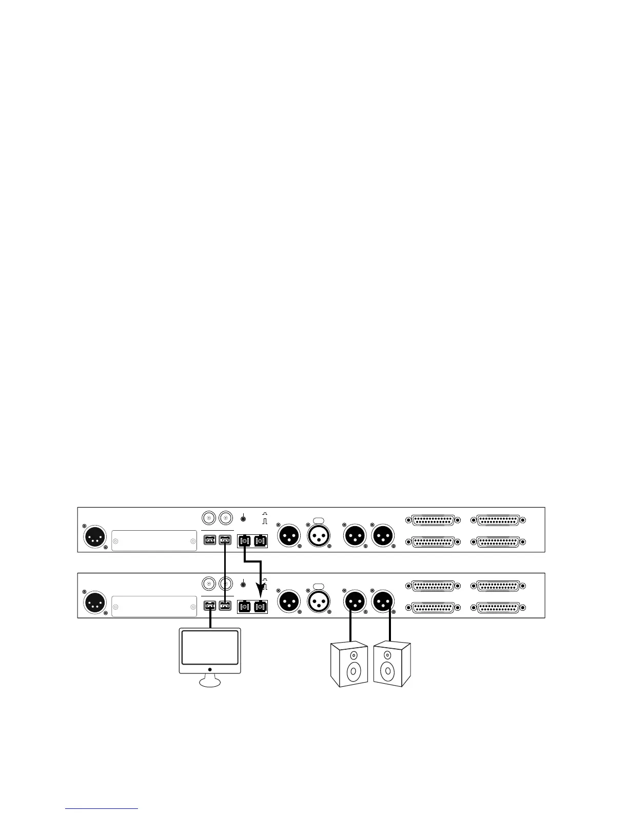
Multi-Unit Cascading Setup – FireWire Host Connection
This diagram illustrates how two Apollo 16 units are connected together into an aggregated interface for 32
simultaneous analog inputs and 32 simultaneous analog outputs using FireWire 800 to connect to the host
computer.
Important: For complete details about system operation when multi-unit cascading, see the Apollo
Software Manual.
Cables Required:
• One FireWire 800 cable for connecting to the host computer
• One FireWire 800 Cable for connecting between the two interfaces
• One MADI optical cable for connecting between the two interfaces
(single or dual MADI cables can be used)
Key points for this example:
• One unit is designated as the “Monitor” (the master unit – where monitor connections are made)
• One unit is the “Expander” (the slave unit – with higher numbered I/O)
• The Monitor unit is connected to the host computer via FireWire 800
(either Apollo 16 FireWire port can be used for this connection)
• The Expander unit is not connected to the host computer
• One FireWire 800 cable must be connected between the Expander and Monitor units
(either Apollo 16 FireWire port can be used for this connection)
• One MADI optical cable must be connected from the MADI OUT of the Expander unit to the MADI IN of
the Monitor unit
• Monitor and cue outputs are connected to the Monitor unit only
POWER OUT
ON
OFF
IN
75 OHM TERM
WORD CLOCK
FIREWIRE
UNIVERSAL AUDIO, INC.
MON OUT (R) 2 MON OUT (L) 1
LINE OUT 1-8 LINE IN 1-8
LINE IN 9-16
MADI OUT MADI IN
AES/EBU OUT AES/EBU IN
PUSH
LINE OUT 9-16
1394 800 (1) 1394 800 (2)
POWER OUT
ON
OFF
IN
75 OHM TERM
WORD CLOCK
FIREWIRE
UNIVERSAL AUDIO, INC.
MON OUT (R) 2 MON OUT (L) 1
LINE OUT 1-8 LINE IN 1-8
LINE IN 9-16
MADI OUT MADI IN
AES/EBU OUT AES/EBU IN
PUSH
LINE OUT 9-16
1394 800 (1) 1394 800 (2)
Expander Unit
Monitor Unit
FireWire 800
Computer
IMPORTANT: Connect speakers
and cue outputs to monitor unit only
Apollo 16 Multi-Unit Wiring
FireWire Host Connection