Apollo 16 Hardware Manual Front Panel 10
Front Panel
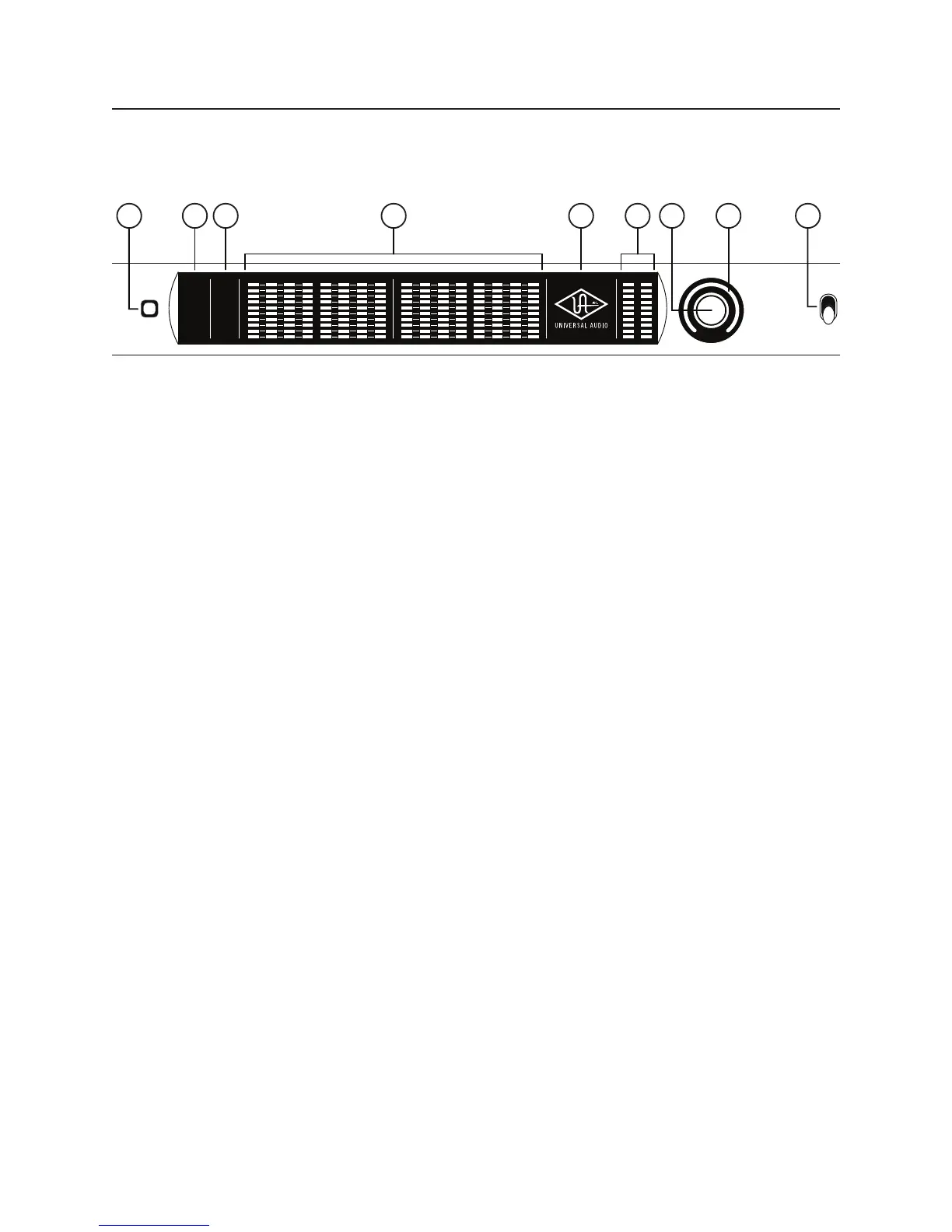
This section describes the features and functionality of all controls and visual elements on the Apollo 16 front
panel. Note that most front panel functions can be controlled remotely with the Console software application.
METER I/O
POWER
OFF
METER
1 2 3 4 5 6 7 8
C
0
-6
-3
-9
-12
-15
-18
-21
-27
88.2
RATE
44.1
48
176.4
96
192
9 10 11 12 13 14 15 16
C
0
-6
-3
-9
-12
-15
-18
-21
-27
HOST
CLOCK
INT
EXT
METER
IN
OUT
MONITOR
1 2
C
0
-6
-3
-9
-12
-15
-18
-21
-27
1
2 4 5 6 7 93 8
(1) Meter
The METER button determines which signals, either input or output, are displayed by the Channel Meters (4).
Push the switch to toggle the meter display state between Input and Output. The current meter state is dis-
played by the METER indicators (2).
(2) Status Indicators
These indicators display the status of the host computer connection, clock, and signal meters, as described
below.
Host
The HOST indicator displays the status of the connection to the host computer system. The indicator is illumi-
nated when Apollo 16 is connected to, and properly communicating with, the host computer system via FireWire
or Thunderbolt. The indicator is off when the host computer is not detected.
The Apollo 16 software must be properly installed and configured on the host computer to enable communica-
tion, and the HOST indicator must be illuminated to use Apollo 16 with all computer operations. The only time
the HOST link is not required is when Apollo 16 is used without a computer (see “” on page 7).
Clock
The CLOCK indicator displays the status of the Apollo 16 clock. When Apollo 16 is using its internal clock as the
master clock source, the INT indicator is illuminated.
When Apollo 16 is set to use an external clock as the master clock source and a valid clock signal is detected at
the specified port, the EXT indicator is illuminated and white.
If the EXT indicator is illuminated and red, Apollo 16 is configured to use an external clock but it cannot lock
to the specified source, and the internal clock remains active instead. In this situation, if/when the specified
external clock becomes available, Apollo 16 switches back to the external clock, and the EXT indicator is il-
luminated and white.
Note: Apollo 16 can be configured to use its internal clock, or an external clock from the Word Clock or
AES/EBU inputs. The clock setting is configured in the Interface panel of the Console Settings window;
see the Apollo Software Manual for details.