Apollo 16 Hardware Manual Front Panel 11
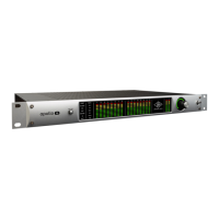
Meter
The METER indicator reflects the state of the Channel Meters (4). The I/O state of the Channel Meters is
switched with the METER button (1).
When IN is illuminated, the Channel Meters display levels at the analog inputs. When OUT is illuminated, the
Channel Meters display levels at the analog outputs.
(3) Sample Rate Indicators
The Apollo 16 sample rate is indicated in this area. The active sample rate is illuminated.
(4) Channel Meters
The sixteen 10-segment LED meters display the signal peak levels for analog channels 1 – 16. The Channel
Meters can display either the input or output levels, as determined by the METER button (1).
Signal levels are displayed at the input to the A/D converters (IN mode) or the output of the D/A converters (OUT
mode). The dB values of the meter LEDs are indicated between the meters for channels 4 & 5 and 12 & 13.
“0” indicates a level of 0 dBFS. When digital clipping occurs, the red “C” LED illuminates. Avoid digital clip-
ping at the channel’s A/D converter by reducing the channel’s level at its source.
(5) Power Indicator (UA Logo)
The Universal Audio logo illuminates when the external power supply is properly connected to an AC outlet and
the power input on the rear of the unit, and the POWER switch (9) is in the up position.
(6) Monitor Output Level Meters
These dual 10-segment LED meters display the signal peak output levels for the monitor outputs at the output
of the D/A converters. These meters are before the Monitor Level control (pre-fader) and reflect the D/A con-
verter levels regardless of the current Monitor Level knob setting (7).
The dB values of the monitor meter LEDs are indicated between the left and right channel meters. “0” indicates
a level of 0 dBFS. When digital clipping occurs, the red “C” LED illuminates. Avoid clipping at the monitor D/A
converters by reducing the monitor bus output level and/or the channels feeding the monitor output bus.
(7) Monitor Level and Mute Knob
This “endless” rotary encoder serves two functions. Rotating the knob adjusts the monitor output level, and
pushing the knob mutes the monitor outputs, as described below.
Monitor Level
The control knob adjusts the signal level at monitor outputs on the rear panel. Although this is a digital control,
the monitor volume is attenuated in the analog domain, after D/A conversion (digitally-controlled analog
volume). This method provides the utmost monitoring fidelity, in contrast to digital volume controls that reduce
levels by truncating the word length (“dropping bits”). The available range is from -INF dBFS (no output)
to 0 dBFS.